Page 4
.
Effective.June.2007
RS-485 PONI
66A2070 Rev. B
Signal Polarity
The data is considered a binary when the voltage level
of the “A” signal is less than the voltage level of the “B”
channel. A binary is considered a Mark or OFF, where as
a.binary.0.is.a.Space.or.ON .
Cabling
The recommended cable for maximum performance of
the RS-485 network has a twisted-pair, 22-AWG stranded
7 x 30 conductors with PVC insulation under aluminum foil
polyester tape, a single 24-AWG stranded 7 x 32 conductor
with PVC insulation and aluminum foil polyester Tape, plus
an all-over braided shield (Belden 306A). Cables with
similar shielding and smaller wire sizes (24 AWG) can be
used for easier wiring. The cable characteristic impedance
should be 20 ohms.
RS-485 Bus Termination
Assuming the characteristic impedance of the cable is
20 ohms, each segment of the RS-485 network should
be terminated with an end-of-line terminating resistor. A
resistor value of 20 ohm should be used at the Master end
of the network as well at the end of the line.
RS-485
PONI
RS-485
PONI
RS-485
PONI
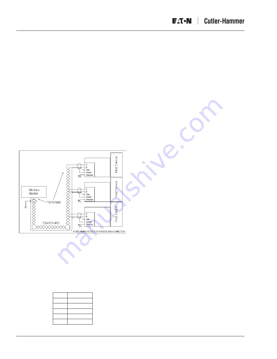
Figure 9. Typical RS-485 PONI Wiring Diagram
Connectors
RS-485 Connector
Figure 9 shows a typical Modbus network where the
RS-485 PONI (Slave) and host devices are connected
to the RS-485 Modbus master. A 5-pin connector pin-out
assignment is as follows:
Pin
Signal
1
A
2
B
3
Common
4
Shield
5
Chassis
Wiring Notes:
. A chassis ground connection is provided as part of the
RS-485 connector. (Refer to the RS-485 Connector
section on Page 4). It should be used only when
mounting the RS-485 PONI to non-metallic surfaces.
2. When mounting the RS-485 PONI to host devices where
the mounting surfaces are tied to the chassis ground, the
“Chassis” ground connection on the RS-485 PONI should
not be connected. Using the metal screws provided will
ensure a proper chassis ground connection.
3. For maximum noise immunity, the chassis ground
terminal should be wired to the closest system chassis
ground with at least a 6AWG stranded copper wire.
(See Wiring Notes and 2.)
4. For maximum noise immunity, the shield of the RS-485
cable should be daisy-chained from one slave device to
another and terminated to chassis ground at the Modbus
master-end of the network (single-point ground).
System Capacity
The RS-485 PONI address can be set between 0 and 99
(decimal). The maximum number of RS-485 PONIs that can
exist.on.a.particular.network.is.99 .
If Modbus slave devices other than RS-485 PONIs exist
within the system, and if their address can be set above 99,
the maximum number of slave devices on the network is 247.
LEDs, Rotary Switches, DIP Switches
As part of the initial setup, the baud rate, address, and
termination resistor must be set to their correct settings.
These switches and indicator LEDs are described as follows:
•
Status LED (µC) (Red)
.
The Status LED indicator lets the user know that the
microprocessor inside of the RS-485 PONI is operating
properly ..It.will.alternate.from.ON.for.1.second.to.OFF.for.
1.second ..
.
Other blinking patterns may be noticed in the event of
an error detected by the RS-485 PONI. Refer to Error
Detection in the Troubleshooting section on Page 6.
•
RS-485 Transmit LED (TX) (Red)
This LED will flash ON when the RS-485 PONI is
responding to a request. The RS-485 PONI only responds
to.requests.to.its.address .
•
RS-485 Receive LED (RX) (Red)
.
The RX LED will flash when the RS-485 PONI detects
that a signal is being transmitted to its address.


