background image

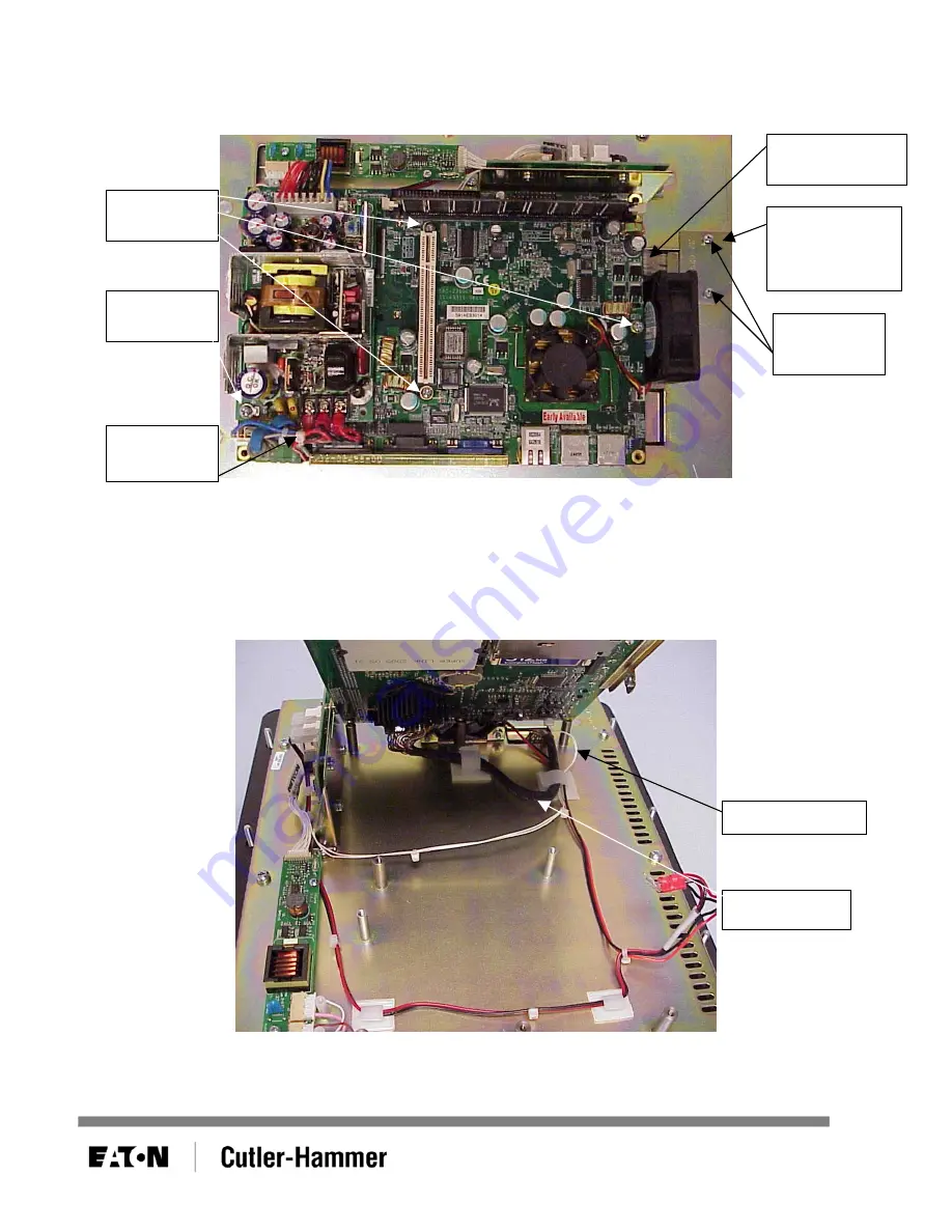
6.  Rotate the unit back 90°. Remove the screws from the CPU circuit board and install one in the power 

supply. Also remove the screws from the touchscreen cable cover plate. Remove the cover plate and 
unplug the touchscreen cable from the CPU circuit board. See Figure 5. 


Remove 
screws 

Touchscreen 
cable cover 
plate 

Touchscreen 
cable

Remove 
screws

Install 
screw

Figure 5 

7.  Cut the tywrap joining the red and black wires (coming up from the bottom of the board) to the cable 

harness on the power supply. Be careful not to nick any of the other wires in the bundle when cutting 
the tywrap. Disconnect the red and black wires from the power supply. See Figure 5. 

8.  Gently tilt the circuit board up along the fan edge of the board and disconnect the video cable and 

inverter cable from the board. See Figure 6. The CPU circuit board is now free from the unit. 


Video cable

Inverter cable

Cut 
tywrap 

Figure 6 

February 2006 

Page 4 of 9 

01-50605-00


Содержание Cutler-Hammer PanelMate ePro PS 7685T-12...

Страница 1: ...re the same Contents Tywrap Backlight Disposable Anti static Wrist Strap Caution Electrostatic Discharge ESD can damage static sensitive electronic components You should perform these procedures only...

Страница 2: ...ove the chassis cover from the electronics module by unscrewing the five screws at the back of the unit and the single screw on the connector side of the unit See Figure 1 Screws Figure 1 3 Remove the...

Страница 3: ...wer supply See Figure 3 Power supply screws Figure 3 5 Gently lift the power supply at an angle to expose the screw underneath See Figure 4 Remove the screw and lower the power supply back in place Sc...

Страница 4: ...5 7 Cut the tywrap joining the red and black wires coming up from the bottom of the board to the cable harness on the power supply Be careful not to nick any of the other wires in the bundle when cutt...

Страница 5: ...ay plate Cable clips Inverter board Touchscreen cable Video cable Screws Backlight cables Figure 7 10 Remove the video cable from the two cable clips Remove the screws along the top and bottom edge of...

Страница 6: ...the display See Figure 8 Screws Figure 8 14 As you remove the display from the display plate carefully pull the video cable and the backlight cables through their respective openings in the plate Feb...

Страница 7: ...uring removal can cause the lamps to break possibly leaving broken glass inside the display 17 Gently and carefully insert the new backlight cartridge into the display Slide the backlight cartridge ve...

Страница 8: ...the small white standoffs See Figure 7 22 Reattach the inverter board See Figure 7 23 Reattach the display plate to the front panel making sure to feed the touchscreen cable through the opening in th...

Страница 9: ...nd black wires to the power supply Red going to the 24V screw terminal and black going to the 0V screw terminal See Figure 5 29 Reattach the power supply See Figure 4 and Figure 3 30 Reattach the stan...

Отзывы: