


IM05805001K
3
Effective November 2003
3.4 Line
Voltage
The
LMR
monitors the 3-phase line voltage via three
control transformers, TR1, TR2 and TR3. If power is
present, the ‘POWER ON’ LED will illuminate on the
membrane faceplate.
The 3-phase voltage can be viewed on the LCD display
using the black ‘STEP’ pushbutton on the flange of the
controller or the UP/DOWN arrow keys on the membrane
faceplate, refer to Section 4.3.
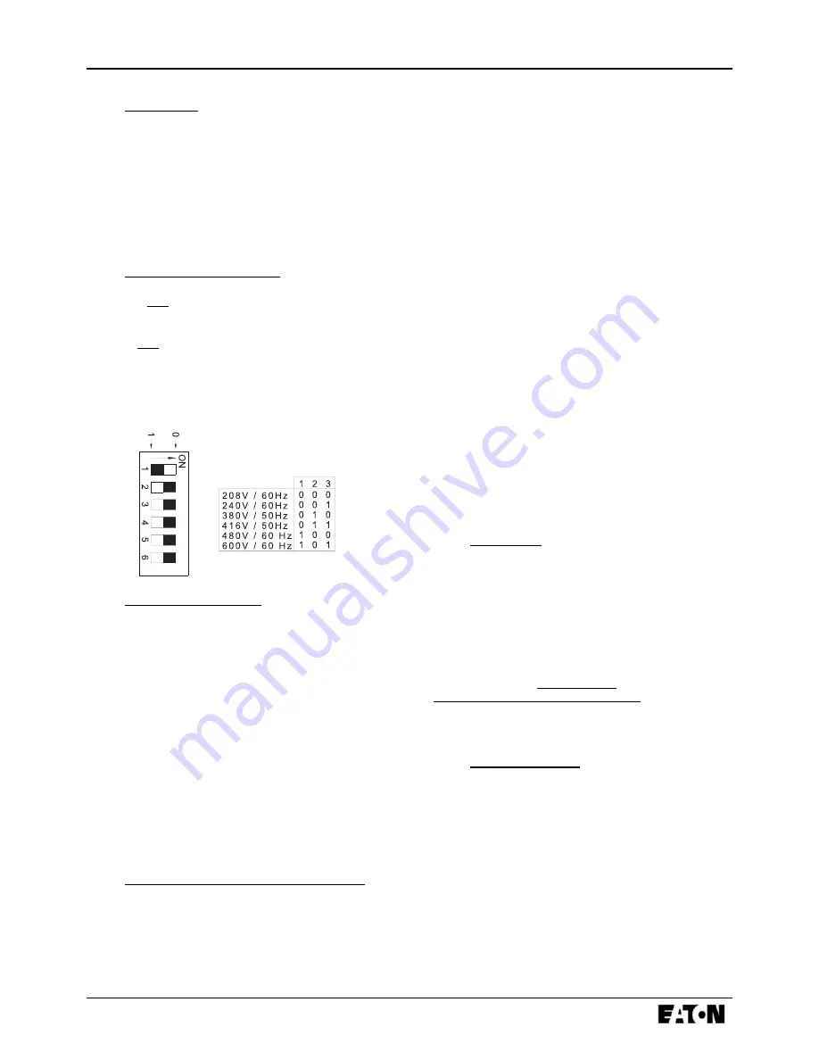
3.5
Phase Reversal DIP Switch
DIP Switch DP2, located on the main motherboard, allows
for correction of the incoming cable rotation. If the Phase
Reversal LED is ON, yet the motor is rotating in the proper
direction, DP2 can rectify the situation.
The settings for DP2 ( Switches 4, 5,6) are as follows:
100
Phase ABC Rotation
000
Phase CBA Rotation
3.6
Locked Rotor Protector
Selection and adjustment of the LRP are factory set and
cannot be modified in the field. The purpose of this device
is to trip the Circuit Interrupter (CB) if motor locked rotor
current, typically 600% of full load amperes, is maintained
between 8 and 20 seconds.
The Locked Rotor Protector is an integral component of the
main controller card. The locked rotor current is detected
via the current transformers mounted in the enclosure.
Refer to the schematic, Figure 3, page 15, for details.
Once the controller trips after a locked rotor condition, upon
resetting the main switch, the ‘LOCKED ROTOR TRIP’
LED will be illuminated and the LCD display will indicate
‘Locked Rotor Trip / Press Reset’. Pressing the RESET key
on the membrane faceplate will initialize the system and the
controller will be ready for use.
3.7
Main Isolating Switch/Circuit Interrupter
The main isolating switch (MIS) is intended for isolating
an electric circuit from its source of power. It has no
interrupting rating and must be externally operable.
The circuit interrupter (CB) is used to disconnect a running
pump motor, if necessary. The CB also provides short
circuit protection for the controller and the pump motor and
operates in conjunction with the Locked Rotor Protector
(LRP). In case of a short circuit the CB will trip
instantaneously. In the case
of seizure of the pump or motor while starting or running,
the LRP will trip the CB, via a shunt trip, within 20 seconds,
as per NFPA, pamphlet No. 20 standards.
When necessary, a current limiter attachment may be
mounted on the bottom of the CB to increase the
interrupting capacity.
If one or more of the current limiter fuses blows, then the
cause must be repaired immediately and new current
limiters installed when repairs are complete.
The isolating switch and circuit interrupter are operated and
interlocked with a single, externally mounted handle. When
moving the handle from OFF to ON, the sequence is such
that the isolating switch is ON first, followed by the circuit
interrupter. When moved from ON to OFF, the circuit
interrupter is opened first followed by the isolating switch.
The operator is interlocked so that the enclosure door cannot
be opened with the handle in the ON position, except by
qualified electrical personnel by use of a defeater screw
located on the side of the operator handle.
3.8 Contactor(s)
The contactor(s) [M, in full voltage and soft start controllers;
1M & 2M, in part winding; M & A, in primary resistor; R,
S & Y, in autotransformer; 1M, 2M, 1S & 2S, in Wye-Delta]
connects the pump motor to the supply, under the control
of the pressure switch, ‘START’ pushbutton(s) or
emergency handle.
The contactor coil(s) are connected to the supply voltage
of the controller. If a replacement coil is ever required,
its voltage rating must be correctly ordered. One auxiliary
contact provides a signal for supervisory purposes to indicate
that the pump is running and one contact is connected to the
LMR
controller card for feedback purposes.
3.9 Emergency
Handle
When pushed and turned counterclockwise, this handle
mechanically closes the power contactor and starts the fire
pump motor, provided there is electrical power available
and the MIS and CB are closed.
The microswitch (MSH), is actuated early in the stroke of
the emergency handle. The MSH operates relay 1CR &
4CR, on the relay board, in an attempt to close the contactor
electrically before the power contacts can close mechanically
by means of the handle. Without pushing the handle in the
full stroke, the pump should continue to run and can be
stopped by the STOP pushbutton. If the pump does not
Содержание Cutler-Hammer LMR
Страница 2: ...Effective November 2003 ...
Страница 6: ......
Страница 20: ...14 IM05805001K Effective November 2003 8 FIGURE 1 MAIN TERMINAL BLOCK TB1 9 FIGURE 2 RELAY CARD ...
Страница 21: ...IM05805001K 15 Effective November 2003 10 FIGURE 3 TYPICAL SCHEMATIC ...
Страница 22: ...16 IM05805001K Effective November 2003 11 FIGURE 4 MAIN DISPLAY PANEL 12 TABLE 1 POWER WIRE CABLE REFERENCE ...
Страница 23: ...IM05805001K 17 Effective November 2003 13 FIGURE 5 LMR PROGRAMMING MENU ...
Страница 27: ...IM05805001K 21 Effective November 2003 18 FIGURE 7 FDF SCHEMATIC ...
Страница 28: ...22 IM05805001K Effective November 2003 19 FIGURE 8 FDF MAIN TERMINAL BLOCK TB1 20 FIGURE 9 FDF RELAY CARD ...
Страница 30: ...24 IM05805001K Effective November 2003 22 FIGURE 10 FDM MEDIUM VOLTAGE DIMENSIONS ...
Страница 31: ...IM05805001K 25 Effective November 2003 23 FIGURE 11 FDM SCHEMATIC ...
Страница 32: ...26 IM05805001K Effective November 2003 24 FIGURE 12 FDM MAIN TERMINAL BLOCK TB1 25 FIGURE 13 FDM RELAY CARD ...
Страница 37: ...IM05805001K 31 Effective November 2003 ...


