


Page 10
\
'
\
\\
Gnd Fault
\ \
Time
�
Sec.
""'
I I
I
I
I
I
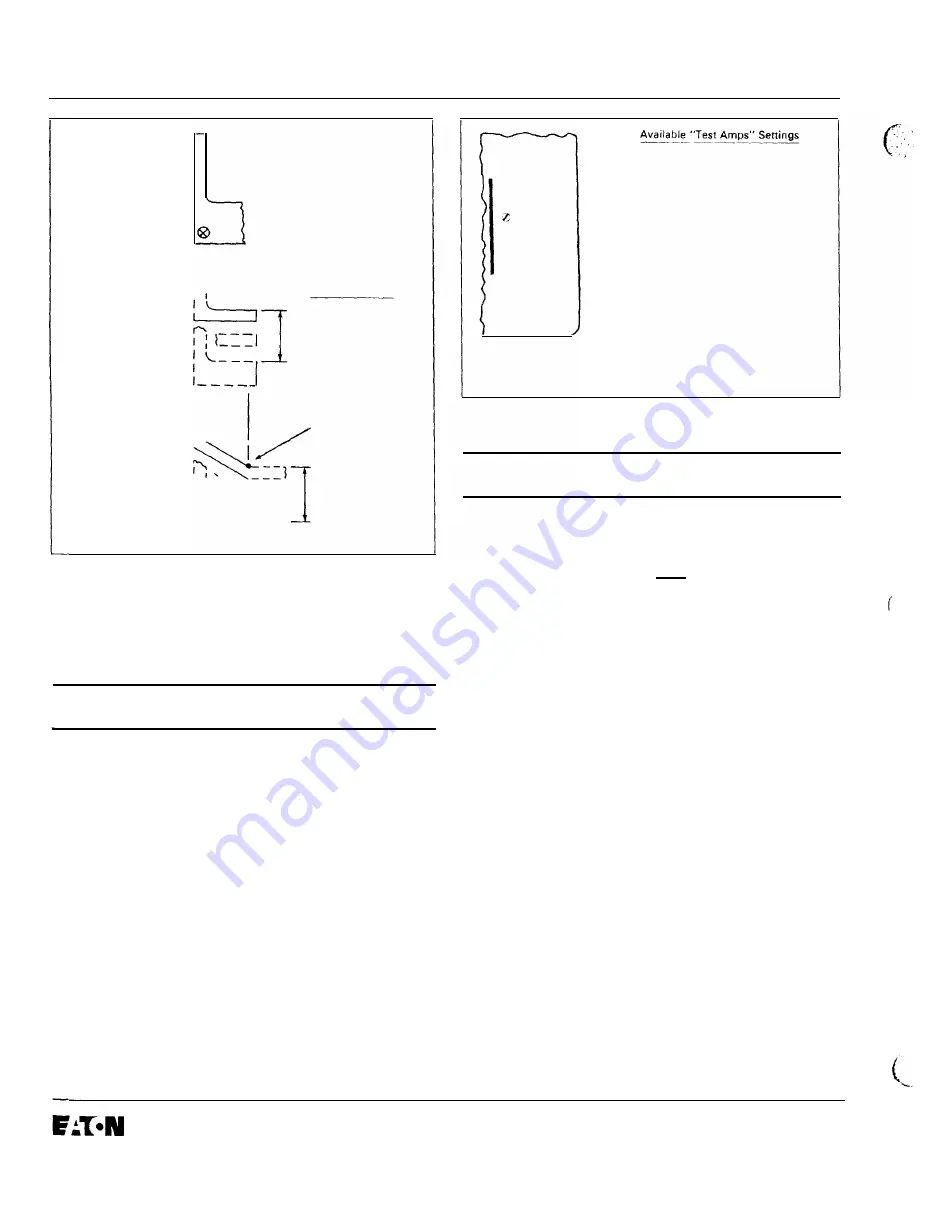
Available Senings
.1 .
.
2
..
3
. .
4
..
5
Seconds with
Flat Response
,__I
I
I
I 1
l't Shape
I 1
Returns to Flat
I
Response at
Approximately
I
I
'
I:
........... ....
I
.1*,.3*,.5*
I
'
'f
.
....
'
Seconds
With
0.6251n
"•"In Viewing Window ' , ' .... I
Ft Shape
Indicates
'' .._ -
--j
l't
Shape
'----
Fig. 4.
7
Ground Fault Time Delay Settings
Note: See also Section 3.6 on Zone Interlocking.
5.0 TEST PROCED U R ES
5.1 General
A
DANGER
DO NOT ATTEMPT TO I N STALL, TEST OR PERFORM
MAIN TENANCE O N EQUIPMENT WHILE IT I S ENER
G IZED. D EATH OR SEVERE PERSONAL INJURY CAN
R ESULT FROM CON TACT WITH ENERGIZED EQUI P
MEN T.
DE-ENERGIZE THE CIRCUI T AND DISCONNECT THE
CIR CU I T BREAKER BEFORE PERFORMING MAIN TE
N A N CE O R TESTS.
As illustrated in Figs. 1 and 5, an integral test panel is
provided to test the Digitrip R MS 510 Trip Unit.
Several no-trip settings are provided to check the trip unit
operation without actually tripping the circuit breaker.
Breaker Trips
At
6T and GFT
Test Amps
(illCD
x 10
Test@
0
Trip
® 0
Reset
Unit
0
Status
I.L. 29-8858
<D
"6T" =Phase Current Test at
6xln and
TRIPS breaker;
"1, 2. 3, 8
or
10"
xI =Phase
Current Test . NO
'b
reaker
TRIP;
"GFT" =Ground Current Test
and
TRIPS breaker;
"GF" =Ground Current Test -
NO breaker
TRIP.
See Section
5.4.3
for inser
vice test trip limitations.
®
Push, then release Trip Reset
button
to reset Trip Unit.
Required following all
automatic trip and test
operations.
@ Push. then release Test
button to test. Test operation
begins with release of
pushbutton.
Fig. 5
Integral Test Panel (Lower Right Corner of Trip
Unit)
A
CAUTION
TESTING A CIRCUIT BREAKER UNDER "TRI P CON
DI TIONS" WHILE I T IS IN SERVICE A N D CARRYING
LOAD CURRENT, WHETHER DONE BY I N TERNAL
OR EXTERNAL MEANS, IS NOT R ECOMMEN DED.
A N Y TRIPPING OPERATION WILL CAUSE DISRUP
TION OF SERVICE AND POSSIBLE PERSONAL
INJURY RESULTIN G FROM U N NECESSARY SWITCH
ING OF CONNECTED EQUIPMEN T.
TESTING OF A CIR CUIT BREAKER THAT RESULTS
IN THE TRIPPING OF THE CIRCUIT BREAKER
SHOULD BE DONE ONLY WITH THE CIRCUIT
BREAKER IN THE "TEST" OR "DISCONNECTED"
CELL POSITIONS OR WHILE THE CIRCUIT
BREAKER IS ON A TEST BENCH.
To preserve the primary protection function of the trip
unit, all in-service testing under "Trip" or "No-Trip" condi
tions are only performed at load current values no greater
than 50% of the Long Delay Current Setting,
1,.
Any
attempt to conduct in-service testing when the load cur
rent exceeds 50% of
1,,
will not be executed by the trip
unit.
Since the Digitrip RMS 510 Trip Unit is completely self
powered using energy derived from the current sensors
installed in the circuit breaker, all in-service tests con
ducted should be conducted with the auxiliary control
power module, shown in Fig.
7,
plugged into the trip unit.
This action will avoid difficulties caused by load current
levels that are too low to operate the trip unit.
Effective May 1997
.
www
. ElectricalPartManuals
. com
Содержание Cutler-Hammer Digitrip RMS 510 Trip Unit
Страница 17: ...I L 29 8858 Page 17 NOTES Effective May 1997 w w w E l e c t r i c a l P a r t M a n u a l s c o m ...
Страница 18: ...Page 18 I L 29 8858 NOTES Effective May 1997 w w w E l e c t r i c a l P a r t M a n u a l s c o m ...
Страница 19: ...I L 29 8858 Page 19 0 NOTES Effective May 1997 w w w E l e c t r i c a l P a r t M a n u a l s c o m ...


