9
INM F890 Rev 1
78
Segment 3 -
66
Segment 7 -
73
Segment 4 +
61
Segment 8 +
74
Segment 4 S
62
Segment 8 S
75
Segment 4 -
63
Segment 8 -
5 .6 Cable Screen / Ground Connections
For revision E .0 or higher units
– Provisions have been made to facilitate tying the
8 screens together and bringing them to the common Screen Ground terminal 53.
This is a user selectable option that is determined based on the position of the jumper
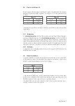
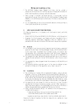
installed in the “Shield Ground Option” connector. Figures 7a and 7b illustrate the two
possible positions for the jumper. The carrier is delivered with the jumper installed as
shown in figure 7b. As indicated in the text on the jumper, the screens are isolated.
To tie the 8 screens together and route them to the SG terminal, remove, reverse and
reinstall the jumper as shown in figure 7a. The arrow next to the text indicates which
direction to install the jumper into the connector for the indicated function.
When using the screen grounding facility on the F890 carrier, the jumper must be
installed correctly (Figure 7a) and an Instrumentation Ground must be routed to
Terminal 53 . Fieldbus segments require proper grounding in order to function properly,
Figure 7a
Figure 7b
For earlier units,
the segment screens are not linked together nor tied to a common
ground connection, so screen grounding must be done externally from the carrier. The
carrier revision is on the board surface between the two F80x modules (see figure
2). No revision number existed before revision E.0. If the screens of the fieldbus
cables are required to be earthed in the equipment cabinet housing the F890 system,
a separate earth bar, connected to local instrumentation earth, should be used.
5 .7 Chassis Ground Connection
The chassis of the carrier should be connected to a Safety or Instrumentation Ground
using either of the two screw terminals 51 or 52. This ground is needed for the F890
system to meet Electromagnetic Compatibility and Electrical Safety requirements.


