IF 1619 • 05/18
Copyright
©
2018, Eaton’s Crouse-Hinds Division Page 9
5. MAINTENANCE
5.1 DRIVE MAINTENANCE
Periodic cleaning of the drive fan and heat sink is recommended. Removal of
the drive from the enclosure is recommended to ensure debris does not obstruct
the cooling system. Refer to the drive manufacturer’s manual for additional
maintenance recommendations and specific instructions.
5.2 COOLING SYSTEM MAINTENANCE
1. Clean pre-filter periodically. Remove pre-filter and rinse with water as needed.
2. Clean sintered filter as needed. Use of abrasives on the explosionproof filters
may compromise the integrity of the cooling system.
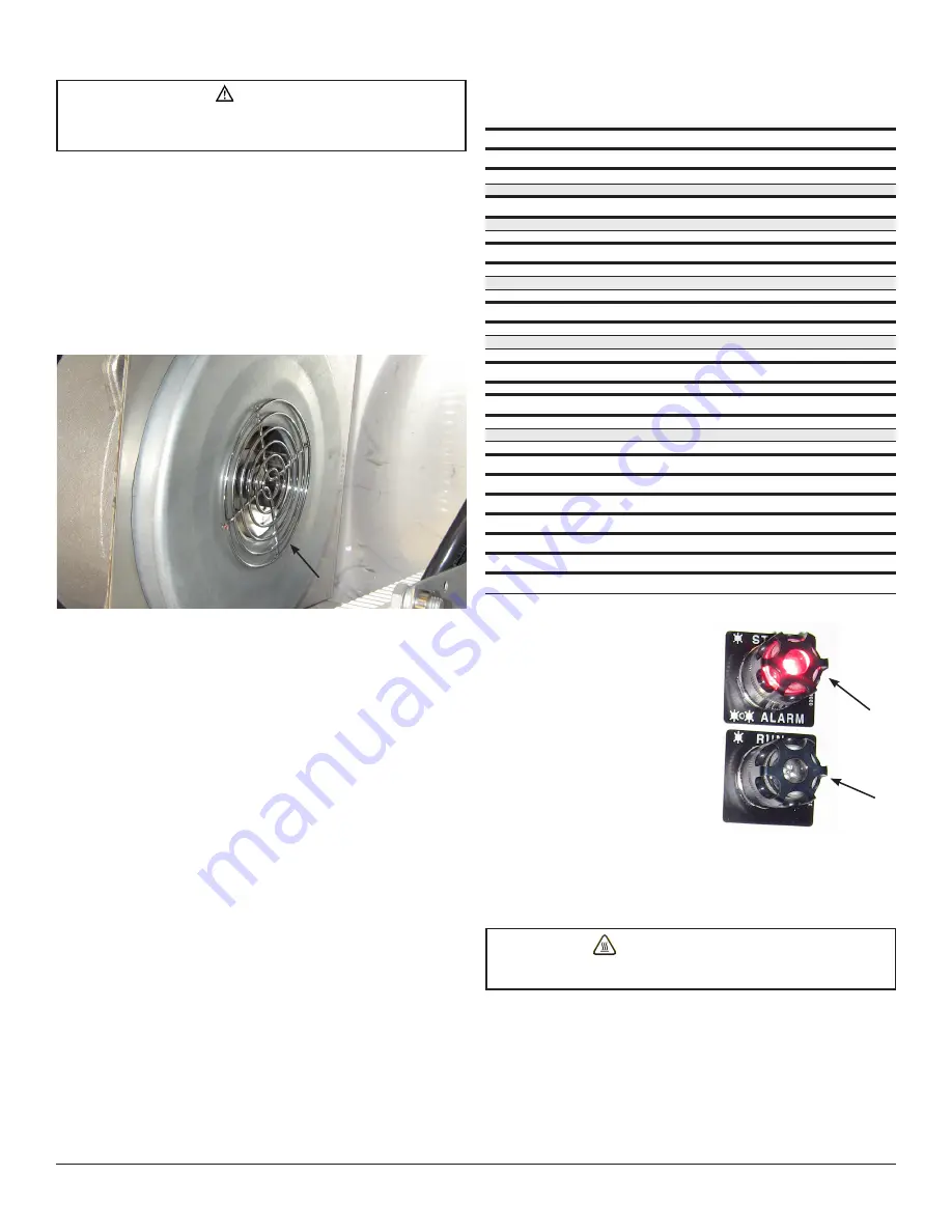
3. Clean/inspect blower intake.
CAUTION
To avoid cooling system malfunction and cooling system failure, be sure to
vacuum debris from the enclosure before energizing. NEVER use forced air for
the removal of debris from this enclosure.
4. Perform visual, electrical and mechanical checks on all components on a
regular maintenance schedule. NFPA 70B recommends maintenance intervals
not exceeding 2 months.
5. Visually check for any damage to the filter assemblies, flat joints, threaded
joints, journal joints and window.
6. Visually check for evidence of excessive heating within the enclosure.
7. Mechanically check that all parts are properly assembled and operating
mechanisms are in proper working condition.
8. Verify airflow provisions are maintained per Section 2.1.
Blower intake
5.3 PERIODIC MECHANICAL MAINTENANCE (TORQUE
VERIFICATION, PUSHBUTTON LUBRICATION,
WINDOW CLEANING)
5.4 STATUS INDICATION -
FILTER MAINTENANCE
There are two (2) lights for the status
indicator - a GREEN light to signify RUN
and a RED light to signify STOP or ALARM
condition.
•
Solid red = power on/drive stopped/fault
•
Solid green = drive running
•
Blinking red = drive running in alarm
mode; maintenance required
•
Lights off = power off
5.5 EXPLOSIVE EVENT
REQUIRED MAINTENANCE
In the event of an explosion within the enclosure, the filter assemblies and pre-
filters must be replaced. Personnel injury or equipment damage may result from
failure to replace the filters with new filters after an explosion occurs within the
enclosure. Inspect all other components and verify that they are in proper operating
condition. Consult Eaton’s Crouse-Hinds Division for replacement parts as needed.
Red
Green
WARNING: BURN HAZARD
To avoid personnel injury, allow sufficient time for the enclosure to cool prior
to servicing.
Torque requirements
Item description
Wire range
Torque requirements
Frame R1 drive (1.5-5 HP)
Line/load
24-12 AWG (0.25-4 mm
2
)
4.4-5.3 in.-lbs. (0.5-0.6 N-m)
Ground
N/A
13 in.-lbs. (1.5 N-m)
Frame R2 drive (7.5-10 HP)
Line/load
20-10 AWG (0.5-6 mm
2
)
10.6-13.3 in.-lbs. (1.2-1.5 N-m)
Ground
N/A
13 in.-lbs. (1.5 N-m)
Frame R3 drive (15-30 HP)
Line/load
10-2/0 AWG (6-70 mm
2
)
11 ft.-lbs. (15 N-m)
Line/load lugs
N/A
25 in.-lbs. (3 N-m)
Ground
N/A
25 in.-lbs. (3 N-m)
Frame R4 drive (40-60 HP)
Line/load
10-2/0 AWG (6-70 mm
2
)
11 ft.-lbs. (15 N-m)
Line/load lugs
N/A
25 in.-lbs. (3 N-m)
Ground
N/A
160 in.-lbs. (18 N-m)
Drive control
I/O terminals
24-12 AWG (0.5-2.5 mm
2
)
5 in.-lbs. (0.5 N-m)
Disconnect
30 amp
14-6 AWG (2.1-13.3 mm
2
)
31 in.-lbs. (3.5 N-m)
60 amp
14-6 AWG (2.1-13.3 mm
2
)
31 in.-lbs. (3.5 N-m)
100 amp
12-1 AWG (3.3-42.2 mm
2
)
35.4 in.-lbs. (4.0 N-m)
Timer relay
20-14 AWG (0.5-2.5 mm
2
)
4.4-7.0 in.-lbs. (0.5-0.8 N-m)
Relay
24-12 AWG
3.5-5.3 in.-lbs. (0.4-0.6 N-m)
Internal ground lug
16-2/0 AWG
120 in.-lbs. (13.5 N-m)
External ground lug
6-1/0 AWG
50 in.-lbs. (5.6 N-m)
Blower manifold
N/A
20 in.-lbs. (2.3 N-m)
Hose clamps
N/A
20 in.-lbs. (2.3 N-m)
Cover bolts
N/A
40-45 ft.-lbs. (54.0-61.0 N-m)


