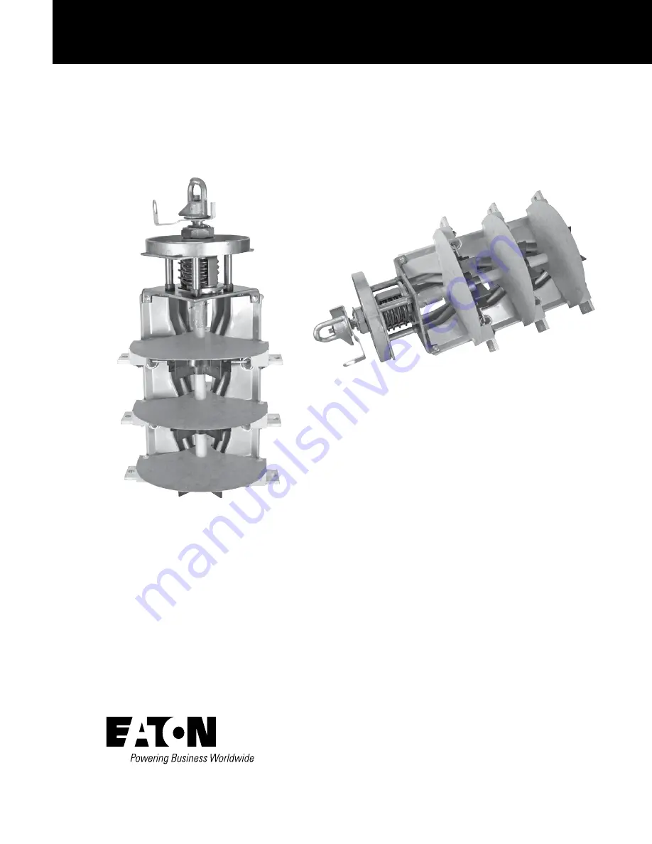
background image

Sectionalizing switch installation instructions

COOPER POWER

SERIES

OEM Equipment 

MN800002EN

Effective March 2016
Supersedes June 2015

Содержание COOPER POWER LS4R Series

Страница 1: ...Sectionalizing switch installation instructions COOPER POWER SERIES OEM Equipment MN800002EN Effective March 2016 Supersedes June 2015...

Страница 2: ...IN ANY EXISTING CONTRACT BETWEEN THE PARTIES ANY SUCH CONTRACT STATES THE ENTIRE OBLIGATION OF EATON THE CONTENTS OF THIS DOCUMENT SHALL NOT BECOME PART OF OR MODIFY ANY CONTRACT BETWEEN THE PARTIES...

Страница 3: ...Std C37 71 2001 standard 2 Ratings and characteristics table per IEC 60265 1 2 Dimensional information 2 INSTALLATION PROCEDURE Bolt In assembly 4 Ring Mount assembly 5 Connect internal leads 6 RECOM...

Страница 4: ...n Safety information DANGER Hazardous voltage Contact with hazardous voltage will cause death or severe personal injury Follow all locally approved safety procedures when working around high and low v...

Страница 5: ...aded activating mechanism ensures quick loadbreak action and positive contact engagement through all positions The Make Before Break MBB switches provide uninterrupted power during switching Read this...

Страница 6: ...n phases kV 95 125 150 Across open contacts kV 95 125 150 Power Frequency 1 minute To ground and between phases kV 35 60 70 Across open contacts kV 35 60 70 DC Withstand 15 minutes To ground and betwe...

Страница 7: ...n be used on 14 gauge 075 inch 1 9 mm to 25 inch 6 4 mm thick frontplate 14 gauge shown 3 Optional padlock handle is available See catalog section CA800005EN Table 6 and Figure 6 4 See catalog section...

Страница 8: ...ng is accomplished with O rings on the operating shaft and gasketed sealing gland secured on the outside of the tank with locking nut 5 Optional install spring small end toward end of shaft and limit...

Страница 9: ...ance zone and have an insulated barrier between them and the switch This barrier will deflect any gas bubbles generated by the switch operation The outline drawing shown in Figure 6 describes the swit...

Страница 10: ...B A A A A COIL B C COIL C COIL V BLADE MAKE BEFORE BREAK A C B A C B A C B A C B AB C B C OPEN A C LINES A B TO C LINE A ONLY LINE B ONLY TO C TO C OPEN ALL B A C COIL T BLADE BREAK BEFORE MAKE A C B...

Страница 11: ...d training may cause excess cantilever force and difficulty in switch operation Figure 6 Arc clearance zone Figure 7 View of tank front with optional limit plate positioned over pin Note With limit pl...

Страница 12: ...next position could jam the mechanism making the switch inoperable If the handle stops jams in a position between the designated marked positions stop switching operation and consult the factory prio...

Страница 13: ...adbreak devices Failure to follow this warning could result in equipment damage severe injury or death WARNING Hazardous voltage Do not operate loadbreak equipment if a fault condition is suspected Do...

Страница 14: ...This page is intentionally left blank 10 SECTIONALIZING SWITCH INSTALLATION INSTRUCTIONS MN800002EN March 2016...

Страница 15: ...This page is intentionally left blank 11 SECTIONALIZING SWITCH INSTALLATION INSTRUCTIONS MN800002EN March 2016...

Страница 16: ...es Eaton com cooperpowerseries 2016 Eaton All Rights Reserved Printed in USA Publication No MN800002EN Rev 01 Supersedes MN800002EN Rev 00 SAFETY FOR LIFE Eaton is a registered trademark All trademark...

Отзывы: