Eaton AFL Скачать руководство пользователя страница 9

9

Instruction Booklet 

IB182047EN

Effective February 2018

Arc flash limiter (AFL)  

conversion system 


EATON

 www.eaton.com

Appendix A. Field taping of joints and  

connections

m

 WARNING

INSTALLATION OF THIS AFL CONVERSION SYSTEM MUST BE PERFORMED 

ONLY BY QUALIFIED PERSONNEL THAT ARE TRAINED FOR THE 

INSTALLATION

The figures contained in this Appendix give general rules to follow 

when field taping joints and connections .  These are provided for 

reference only .

otee:

N

During the initial installation of the AFL Conversion System, all joints 

and connections will made by qualified personnel that are trained for the 

installation .

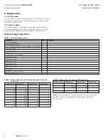
Figure 10. T-joint field taping methods.

Figure ??. T-joint Field Taping Methods.

DRAFTER

MODEL FILENAME

ENGINEER

ENGINEERING CHANGE NOTICE NO.

THIS DOCUMENT,  INCLUDING THE  DRAWING AND  INFORMATION 

CONTAINED THEREON,  IS CONFIDENTIAL AND IS THE EXCLUSIVE 

PROPERTY OF  EATON CORPORATION,  AND IS MERELY ON LOAN 

AND SUBJECT TO RECALL BY EATON CORPORATION AT ANY TIME.

EATON CORPORATION - CONFIDENTIAL AND PROPRIETARY

DATE

DATE

MODEL REV

P. KIM

4/10/1991


RP

RE

TE

D

1

99

4

TH

1

MATERIALS


FILLER - A PUTTY-LIKE MATERIAL.TRADE NAMES: DUCTSEALER, DUCT SEAL, EATON. NO. 

53351BB AND 53351WX.

INSULATING - HIGH VOLTAGE EPR INSULATING TAPE. TRADE NAME: SCOTCH 130C TAPE, 

EATON. NO. 45151SE.


DEFINITIONS


JOINT - AREA TO BE COVERED WITH TAPE. CONSISTS OF BARE CONDUCTOR AND 1.5 

INCHES OF ANY PRE-INSULATION NEXT TO THE BARE CONDUCTOR.


PRE - INSULATION - ANY INSULATING COVERING OR COATING SUCH AS EPOXY COATING 

OR INSULATING TUBING ADJACENT TO AN EXPOSED CONDUCTOR PRIOR TO TAPING.


PAD - ANY INSULATING TAPE APPLIED WHICH IS WIDER THAN ONE  INCH. INCLUDES A 

BAND OF TAPE CONSISTING OF ONE OR MORE TURNS WRAPPED DIRECTLY ON TOP OF 

EACH OTHER.


LAYER - INSULATING TAPE, 1 INCH WIDE, WRAPPED FROM ONE END OF THE JOINT TO 

THE OTHER, (OR TO A PAD) SO EACH SUCCEEDING TURN LAPS THE PREVIOUS TURN BY 

THE AMOUNT SPECIFIED IN THE CHART.                     


OVERLAP - A SPECIFIED DISTANCE MEASURED ALONG THE PRE-INSULATION STARTING 

FROM THE POINT WHERE THE PRE-INSULATION ENDS AND THE EXPOSED CONDUCTOR 

BEGINS.


METHODS


GENERAL


1. ELONGATE INSULATING TAPE 10 TO 25 PERCENT DURING APPLICATION TO INSURE A 

SMOOTH, TIGHT FIT. ON PADS ELONGATE CORNERS ONLY.

2. SHOULD A TAPE ROLL EXPIRE, START THE NEW ROLL BY OVERLAPPING THE PREVIOUS

END BY .5 TURN.


"T"-JOINTS, WITH-HARDWARE


1. CLEAN AREA OF DIRT AND FOREIGN MATTER

2. WIPE PREINSULATION WITH ISOPROPYL ALCOHOL

3. APPLY FILLER OVER BARE CONDUCTOR AND HARDWARE TO COVER AND SMOOTH OUT

THE SURFACE. BLEND CONTOUR INTO PRE- INSULATION SURFACES. TRY TO PREVENT 

AIR POCKETS. COVER CONDUCTORS AND HARDWARE WITH AT LEAST .12 INCH OF FILLER

PER FIG. 1.

4. APPLY 3.00X.030 THICK PAD #1 OVER CENTER OF JOINT WITH 1 1/4 LAPS (FIG. 2). APPLY 

3.00 X .030 THICK PAD #2 STARTING .50 INCH FROM CENTER AND EXTENDING OVER 

PREINSULATION AT LEAST 1.0 INCH WITH 1 1/4 LAPS. APPLY 3.00 X .030 THICK PAD #3 

STARTING 1.00 FROM PAD #2 AT CENTER AND EXTENDING 1.00 IN. OVER PREINSULATION 

PER FIG. 3.

5. APPLY (3) 6.00 IN. WIDE X 12 IN. LONG X .030 IN THICK PADS (PAD#4) CENTERED ON THE 

MAIN BUS AND EXTENDING 1.50 IN. DOWN RISER PER FIG. 4.

6. APPLY ONE LAYER OF INSULATING TAPE (1.00X.030) USING 2/3 LAP AND EXTENDING 

0.50 INCH MINIMUM BEYOND THE PADS ON THE PREINSULATION (FIG. 5).

7. APPLY A SECOND LAYER OF INSULATING TAPE (1.00X.030) USING 2/3 LAP AND 

EXTENDING 0.50 INCH MIN. FOR (27KV) AND 1.50 MIN. FOR (38KV) BEYOND THE FIRST 

LAYER ON THE PREINSULATION PER FIG. 5.

2

96

A

N

D

A

S


O

IN

T

3

O

T

E


4

01

6

E

D


F

O

PREINSULATION

PREINSULATION

PREINSULATION

PREINSULATION

PAD #1

FIG. 1: TYPICAL JOINT WITH .12 THK.

MIN. FILLER OVER BARE JOINT.

PREINSULATION

PREINSULATION

PAD #2

PAD #1

PAD #3

FIG. 2: TYPICAL JOINT WITH 3 IN.

WIDE X .030 TAPE OVER FILLER.

PREINSULATION

PAD #4

PREINSULATION

FIG. 3: TYPICAL JOINT WITH Pads #2 & #3

(3 IN. WIDE X .030) TAPE

OVER PAD #1 AND FILLER.

1.0

1.0

1.0

1.0

Fig 4: TYPICAL JOINT WITH PAD #4

(3) 6.0 X .030 PIECES OF TAPE.

PREINSULATION

PAD #3

PAD #4

PAD #1

FILLER

PAD #2

INSUL.
TAPE

FIG. 5: 2 LAYERS OF 1.0 x .030

TAPE WITH 2/3 OVERLAP.

9.0 (27 kV)
11.0 (38 kV)MIN.

LAP

MAIN BUS/RISER JOINT.

Содержание AFL

Страница 1: ...ents Description Page 1 Introduction 2 2 AFL conversion system and components 3 3 Typical installation performed by qualified personnel 5 4 AFL conversion system control unit 7 5 Maintenance 8 6 Parts List 8 Appendix A 9 Arc flash limiter AFL conversion system ...

Страница 2: ...ost of capital loss of power additional expenses in the use of existing power facilities or claims against the purchaser or user by its customers resulting from the use of the information and descriptions contained herein 1 1 2 Safety precautions All safety codes safety standards and or regulations must be strictly observed in the operation and maintenance of this system m WARNING THE WARNINGS AND...

Страница 3: ...n and a set of current sensors are added to the secondary side of the transformer to feed the ARMS feature on the breaker trip unit In some cases the original discon nect switch is retained The control unit also includes a breaker control switch and breaker status LEDs for breaker control The 520MCV trip unit with Maintenance Mode in the breaker inter faces with the ARMS switch mounted in the cont...

Страница 4: ...ll introduce an increased risk of destructive high voltage transients into the system Transient voltages have been proven to cause transformer failures during switching To mitigate this risk it is highly recommended Eaton Power Systems Engineering PSE conduct a switching transient study to determine the optimal surge protection surge arrester RC snubber and or damping resistor needed to mitigate s...

Страница 5: ... joints and connections and insure they meet the standards identified in NEC Table 490 24 Qualified field service technicians will install the disconnect switch to breaker connections These will usually be copper bus work typically 1 4 x 2 or 1 4 x 3 6 35 x 50 8 mm or 6 35 x 76 2 mm In some cases the connections will be cable instead of copper bus work depending on the rating of the breaker Refer ...

Страница 6: ...th the AFL conversion system it was designed based on the results of the optional study of the customer s existing original electrical system performed by Eaton PSE Figure 7 Typical custom snubber Qualified field service technicians will install the control unit either on the enclosure door or mounted remotely based on the customer s preference If a remotely mounted control unit is selected the co...

Страница 7: ...s 50 51 protection 2 Breaker control switch The breaker control switch is used to open and close the breaker 3 Red indicating LED pushbutton The red indicating LED pushbutton indicates the breaker is closed 4 White indicating LED pushbutton The white indicating LED pushbutton indicates the springs of the breaker are charged 5 Green indicating LED pushbutton The green indicating LED pushbutton indi...

Страница 8: ... 3 Current sensor 3 AFL control unit 120 Vac NEMA 1 1 Copper phase A load 1 Copper phase B load 1 Copper phase C load 1 Copper phase A line 1 Copper phase B line 1 Copper phase C line 1 Phase barrier 2 Nameplate Eaton AFL Assembly 1 Nameplate AFL Ratings 1 Table 2 Torque values for general mounting and screw size conversion Decimal size in Standard size Torque in lbs Torque ft lbs 112 4 40 10 0 8 ...

Страница 9: ...T OVERLAP A SPECIFIED DISTANCE MEASURED ALONG THE PRE INSULATION STARTING FROM THE POINT WHERE THE PRE INSULATION ENDS AND THE EXPOSED CONDUCTOR BEGINS METHODS GENERAL 1 ELONGATE INSULATING TAPE 10 TO 25 PERCENT DURING APPLICATION TO INSURE A SMOOTH TIGHT FIT ON PADS ELONGATE CORNERS ONLY 2 SHOULD A TAPE ROLL EXPIRE START THE NEW ROLL BY OVERLAPPING THE PREVIOUS END BY 5 TURN T JOINTS WITH HARDWAR...

Страница 10: ... 030 THICK PAD 2 STARTING 50 INCH FROM CENTER AND EXTENDING OVER PREINSULATION AT LEAST 1 0 INCH WITH 1 1 4 LAPS APPLY 3 00 X 030 THICK PAD 3 STARTING 1 00 FROM PAD 2 AT CENTER AND EXTENDING 1 00 IN OVER PREINSULATION PER FIG 8 6 APPLY ONE LAYER OF INSULATING TAPE 1 00X 030 USING 2 3 LAP AND EXTENDING 0 50 INCH MINIMUM BEYOND THE PADS ON THE PREINSULATION PER FIG 9 7 APPLY A SECOND LAYER OF INSULA...

Страница 11: ...ated pothead bushing Pothead ground lead must be carried through the Zero Sequence current transformer and solidly grounded on the load side of the ct as shown Use 6 wire with 600 V insulation Power cables Conduit when used Cable connections to switchgear terminals when used with Insulated Pothead Conduit must be terminated and solidly grounded on the load side of the current transformer Zero Sequ...

Страница 12: ...between Eaton and the purchaser THERE ARE NO UNDERSTANDINGS AGREEMENTS WARRANTIES EXPRESSED OR IMPLIED INCLUDING WARRANTIES OF FITNESS FOR A PARTICULAR PURPOSE OR MERCHANTABILITY OTHER THAN THOSE SPECIFICALLY SET OUT IN ANY EXISTING CONTRACT BETWEEN THE PARTIES ANY SUCH CONTRACT STATES THE ENTIRE OBLIGATION OF EATON THE CONTENTS OF THIS DOCUMENT SHALL NOT BECOME PART OF OR MODIFY ANY CONTRACT BETW...

Отзывы: