5
Instruction Booklet
IB182047EN
Effective February 2018
Arc flash limiter (AFL)
conversion system
EATON
www.eaton.com
3.Typical installation performed by qualified
personnel
m
WARNING
INSTALLATION OF THIS AFL CONVERSION SYSTEM MUST BE PERFORMED
ONLY BY QUALIFIED PERSONNEL THAT ARE TRAINED FOR THE
INSTALLATION..
A summary of the typical installation procedures of the AFL conver-
sion system that is performed by qualified field service technicians is
contained in the section below .
These are the typical procedures
.
The actual procedures for a specific installation may vary due to
the components included in the new AFL conversion system, the
original components being replaced, and the existing switchgear
enclosure .
3.1 Typical installation procedure
otee:
N
The order of the following procedures may vary due to the specific
installation .
•
Qualified field service technicians will remove and discard the
existing fuses and other components used for the disconnect
function . Often, this will include “gutting” (removing and discard-
ing) everything in line after the original the disconnect switch .
•
Qualified field service technicians will install the new the basic
mounting structure/platform (usually comprised of custom uni-
strut and brackets) for the new breaker within the switchgear
enclosure . The structure will vary depending on the particular
enclosure and components .
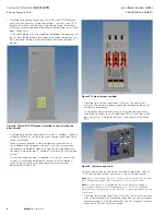
Figure 3. Typical uni-strut and brackets used for mounting the
breaker.
otee:
N
During AFL conversion system installation, qualified field service tech-
nicians will reference NEC Table 490 .24 - “Minimum Clearance for Live Parts”
for all joints and connections and insure they meet the standards identified in
NEC Table 490 .24 .
•
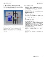
Qualified field service technicians will install the disconnect
switch to breaker connections . These will usually be copper bus
work (typically 1/4 x 2” or 1/4 x 3” [6 .35 x 50 .8 mm or 6 .35 x 76 .2
mm]) . In some cases the connections will be cable instead of
copper bus work depending on the rating of the breaker .
Refer to Appendix A for examples of normal joint and connection
field taping .
Figure 4. Typical copper bus work and connection cables.
•
Qualified field service technicians will install the breaker to the
transformer connections . These will usually be copper bus work
(typically 1/4 by 2” or 1/4 by 3” [6 .35 x 50 .8 mm or 6 .35 x 76 .2
mm]) . In some cases the connections will be cable instead of
copper bus work depending on the rating of the breaker and
transformer .
Refer to Appendix A for examples of normal joint and connection
field taping .
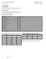
Figure 5. Typical current sensors installed during installation.
otee:
N
In some cases, Eaton may supply custom bus boots to use in place
of field taping if included purchase agreement .
•
Qualified field service technicians will install the red glass poly
(GP03 insulating material) phase barriers between phases A and B
and B and C as per the custom AFL conversion system design .
•
Qualified field service technicians will install the three current
transformers (CTs) and mounting brackets, if applicable, on the
breaker/primary side of the transformer . These will be wired into
the feeder protection relay to provide 50/51 protection .
•
Qualified field service technicians will install the three current
sensors on the secondary side of the transformer . These will be
wired into the trip unit of the breaker to provide instantaneous
breaker reaction .
Line copper bus
Load copper bus
CTs


