background image

28 


4.2 Operating UPS  

Notice:

  Please  switch  off  the  connected  loads  first  before  turning  on  the 

UPS,  and  switch  on  the  loads  one  by  one  after  the  UPS  is  turned  on. 
Switch off all of the connected loads before turning off the UPS. 

Notice:

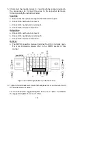
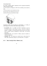
 Power on for the first time 

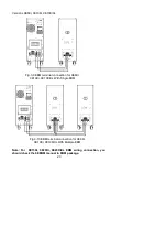
1.  Close the magnetothermic switch located upstream of the UPS. 
2.  Close the input and output switches and insert the battery fuses (if any) 

located on the back of the UPS’s backpack.  
 

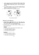
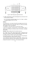
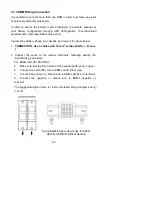
4.2.1 Turning on UPS with mains


Check  that  all  connections  are  correct.  Check  the  breaker  of  external 
battery pack is in “ON” position. 
Set input breaker in “ON” position. At this time the fan begins to rotate. By 
pressing 

 button  continuously  for  more  than  2  second,  the  buzzer  will 

beep once, UPS starts to turn on. 

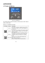
A few seconds  later, the UPS turns into Line mode. If the mains power is 
abnormal, the UPS will transfer to Battery mode without output interruption 
of the UPS. 

4.2.2 Turning on UPS without mains


Check  that  all  connections  are  correct.  Check  the  breaker  of  external 
battery pack is in “ON” position. 

By pressing 

 button continuously for more than  2s, the buzzer will beep 

once, UPS starts to turn on. 

A few seconds later, the UPS turns into Battery mode.  If the mains power 
comes back, the UPS will transfer to Line mode without output interruption 
of the UPS. 

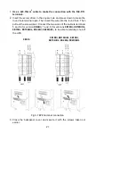
4.2.3 Turning off UPS with mains 

To turn off the inverter of UPS press 

 button continuously for more than 

3s and the buzzer beep once.  

The UPS will turn into standby mode. 

Cut off the mains power supply.  

A few seconds later, LCD display shuts down. 

Содержание 9E 10000i

Страница 1: ...Eaton 9E 10000i 9E10Ki Eaton 9E UPS https eaton power ru catalog eaton 9e eaton 9e 10000i...

Страница 2: ...powerquality eaton com Eaton 9E 6 20kVA...

Страница 3: ...2 Presentation 5 2 1 Model List 5 2 2 Electrical structure 5 2 3 UPS views 7 3 Installation 12 3 1 Unpacking 12 3 2 Package content 13 3 3 Connection 13 4 OPERATION 24 4 1 Display and Buttons 24 4 2...

Страница 4: ...disconnect device shall be incorporated in the building installation wiring for permanently connected equipment The UPS generates hazardous electric voltages inside it even when the input and or batte...

Страница 5: ...leaks of liquid or a white powder residue Make sure that no water liquid in general and or other foreign matter gets inside the UPS Under hazardous conditions turn off the UPS at the 1 0 main power s...

Страница 6: ...4 Level 4 Surge IEC EN 61000 4 5 Level 4 CS IEC EN 61000 4 6 Level 3 MS IEC EN 61000 4 8 Level 3 Voltage Dips short interruptions and voltage variations IEC EN 61000 4 11 Warning This is a product for...

Страница 7: ...4 1 3 Special Symbols The following are examples of symbols used on the UPS or accessories to show you the important information...

Страница 8: ...Combo 0 8 230V 220 240 9E15Ki 15kVA 12kW Combo 0 8 230V 220 240 9E20Ki 20kVA 16kW Combo 0 8 230V 220 240 9E20KiXL 20kVA 16kW Combo 0 8 230V 220 240 9EEBM180 For 9E6Ki 180V 9EEBM240 For 9E10Ki 9E10KiX...

Страница 9: ...nternal power Charger Battery Input Switch Bypass Maintain Switch Output Switch Main power wiring 9E15Ki 9E20Ki 9E20KiXL INPUT OUTPUT N L N L2 L1 L3 Input filter AC DC DC AC Output filter Internal pow...

Страница 10: ...7 2 3 UPS views 2 3 1 UPS Front view Display Multipurpose buttons Wheels front wheels swivel and can be locked fixed rear wheels...

Страница 11: ...S232 communication port Cover for terminals Slot for optional communication card Fuse Cooling fan s Terminals for I O cable connection refer to related section Output switch Earthing screws Manual byp...

Страница 12: ...S232 communication port Cover for terminals Slot for optional communication card Fuse Cooling fan s Terminals for I O cable connection refer to related section Output switch Earthing screws Manual byp...

Страница 13: ...L Without backpanel cover RS232 communication port Input switch USB communication port Cover for terminals Slot for optional communication card Terminals for I O cable connection refer to related sect...

Страница 14: ...2 3 3 EBM Rear view Fuse Cover for terminals Tie wrap hold down Wheels front wheels swivel and can be locked fixed rear wheels Terminals for I O cable connection refer to related section Earthing scre...

Страница 15: ...upward and take out front PE form 4 Put the wood board removed at step2 as figure showed Make sure that the slide rests firmly against the pallet so it remains in place during unloading operations Pul...

Страница 16: ...s Warning Installation must be performed by qualified personnel The first connection to perform is the protective conductor earth cable which must be connected to the screw marketed The UPS when inser...

Страница 17: ...A Three phase Type B The neutral arrangements are altered only if there is an isolating transformer or when the UPS operates with a neutral that is disconnected upstream In any case avoid connecting t...

Страница 18: ...hazardous voltage between all terminals The current rating of T AC contactor should be more than 1 3 times of UPS capacity MAIN INPUT UPS B Q T L N B coil remote switch Q input main switch T AC contac...

Страница 19: ...ide Fig 3 3 Wiring connection Single phase version 9E6Ki only 4 SINGLE PHASE CONNECTION 9E6KI use 3 cables with cross section 6 mm 2 EARTH N and L for the input and 3 cables with cross section 6 mm 2...

Страница 20: ...ase connection 4 SINGLE PHASE CONNECTION 9E10KI 9E10KIXL use 3 cables of cross section 10 mm 2 EARTH N and L for the input and 3 cables of cross section 10 mm 2 for the output EARTH N and L SINGLE PHA...

Страница 21: ...ire to terminal 1 Output line a Connect the earth wire to screw B b Connect the neutral wire to terminal 5 c Connect the live wire to terminal 6 R E P O a The REPO connection between terminal 5 and 6...

Страница 22: ...ONNECTION 9E20KI 9E20KIXL Use 2 cables of cross section 6 mm 2 L2 and L3 and 3 of cross section 25 mm 2 EARTH N L1 for the input N B L1 and N are of greater cross section because in bypass operation t...

Страница 23: ...gency if the stop device is used the REPO control is closed and the UPS goes into stand by mode and the load is completely disconnected Attention before restarting the UPS reset the stop device The ci...

Страница 24: ...into the round hole Then pull out the screw driver Connect the two wires of the cable to terminals 5 and 6 for version 9E6Ki 7 and 8 for versions 9E10Ki 9E10KiXL 9E15Ki 9E15KiXL 9E20Ki 9E20KiXL to be...

Страница 25: ...below 1 CONNECTION Use 3 cables with 10 mm 2 section Earth N and 2 Connect the wires to the relative terminals following exactly the instructions given below For 9E6Ki 9E10Ki 9E10KiXL a Make sure tha...

Страница 26: ...E15Ki 9E20Ki 9E20KiXL EBM wiring connection you should check the 9EEBM manual in EBM package Fig 3 10 EBM terminal connection for 9E6Ki 9E10Ki 9E10KiXL With Mutliple EBM Fig 3 9 EBM terminal connectio...

Страница 27: ...he buzzer will beep once then the UPS system will be turned on Turn off If the UPS is in line battery HE or battery test mode press 3s the buzzer will beep once then the UPS will be turned off Transfe...

Страница 28: ...Inverter Green It indicates that the inverter is OK and the load is supplied from the inverter Note After UPS power on all LEDs will be lightened for 2 seconds and then turn to normal status When UPS...

Страница 29: ...bypass One beep per 1s Note buzzer alarm can be enable disable by function button if buzzer alarm is disabled all present alarm is muted except that the button press still has a tick beep Buzzer alar...

Страница 30: ...nput It indicates information for input Load It indicates information for load Battery It indicates information for battery Load level It indicates the load level Load border will flash if the load is...

Страница 31: ...uously for more than 2 second the buzzer will beep once UPS starts to turn on A few seconds later the UPS turns into Line mode If the mains power is abnormal the UPS will transfer to Battery mode with...

Страница 32: ...S will transfer to maintenance bypass mode Switch off the input and output switch before doing maintenance on the UPS To transfer the UPS back to normal mode switch on the input and output switch and...

Страница 33: ...owing communication ports are present RS232 connector USB connector Slot for optional connectivity cards RS232 or USB communication ports The RS232 and USB communication ports cannot operate simultane...

Страница 34: ...ty of networking environments and with different types of devices Network MS card has SNMP and HTTP capabilities as well as monitoring through a Web browser interface connects to Ethernet network In a...

Страница 35: ...THE DISPLAY DOES NOT LIGHT UP INPUT SWITCH OPEN Close the input switch located on the back of the UPS MAIN CONNECTION CABLE MISSING Check that the power cable is connected correctly NO MAINS VOLTAGE B...

Страница 36: ...emperature of the environment in which the UPS is located does not exceed 40 C THE BUZZER SOUNDS CONTINUOUSLY AND THE DISPLAY SHOWS ONE OF THE FOLLOWING CODES F805 THERE IS A FAULT ON ONE OR MORE OF T...

Страница 37: ...Unbalanced input voltages three phase input A806 E P O control active A80E Overload load 105 A810 Load percentage greater than the user threshold set A60D Batteries missing or Battery Box missing or n...

Страница 38: ...of the Battery Box 180Vdc 240Vdc 240 240Vdc 240 240Vdc Charging current for XL versions only Not applicable 4 4A 5A 5A OUTPUT Nominal voltage Vac Selectable 220 230 240 Frequency Hz Selectable 50 60...

Страница 39: ...harge overcurrent short circuit overvoltage undervoltage circuit breaker Dimensions W x D x H mm 262 x 613x 709 350 x 706 x 818 Weight kg 68 8 86 29 XL 147 160 48 5 XL Operating Temperature 0 o C to 4...

Страница 40: ...37...

Страница 41: ...38 614 06847 03...

Отзывы: