background image

UPS System Installation

4-10 

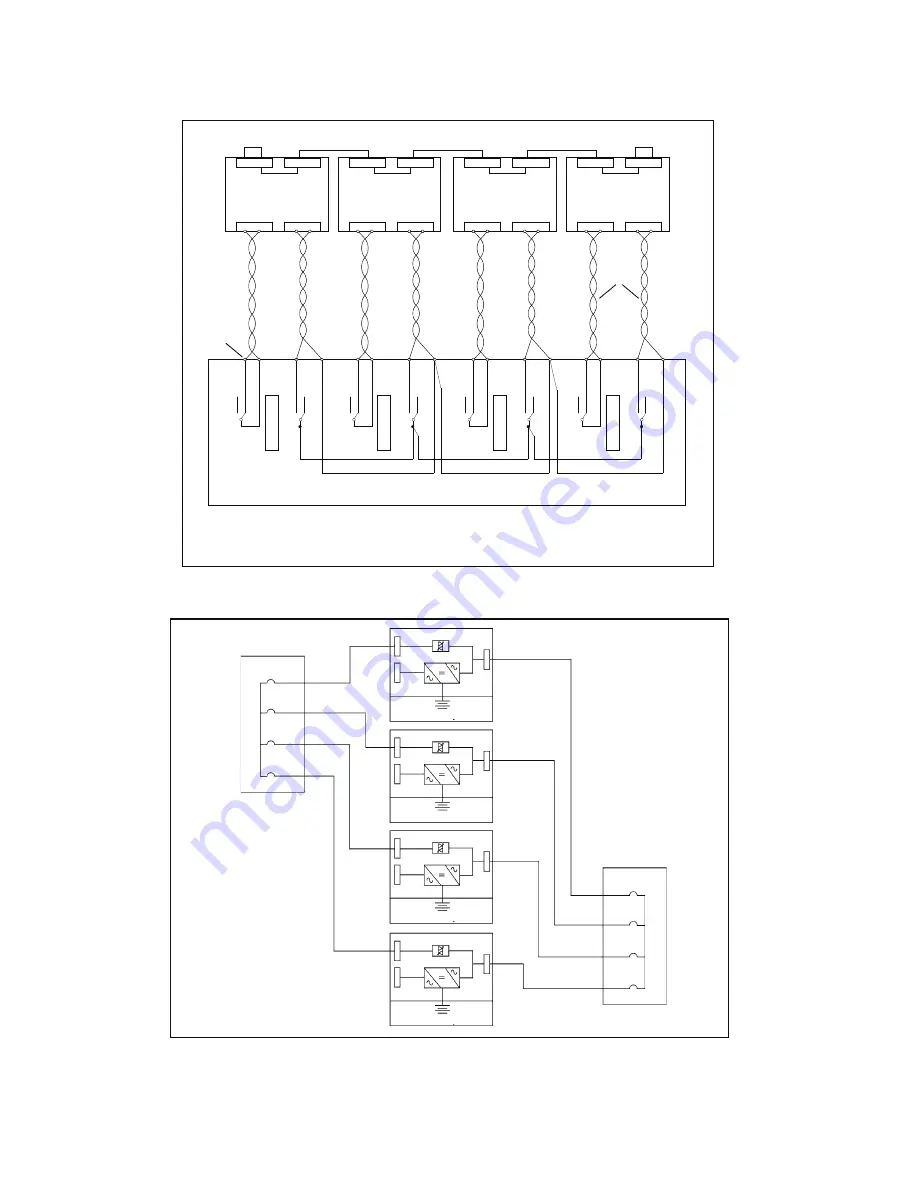
         Eaton 93E UPS (300/400 kVA, 380/400/415V) Installation and Operation Manual

Figure 4-6. Parallel UPS system connections

1A

1B

2A

2B

3A

3B

4A

4B

UPS 1

UPS 2

UPS 3

UPS 4

Outputs from 

UPSs

Bypass  inputs 

to UPSs

Battery

Battery

Battery

Battery

UPS 
System 

Installation

4-

20

Ea

ton

 9E 
UPS (40

–6

0 k

VA, 20
8/22
0V) In

st

alla
tio

n an
d Op
er

ati

on M

anu
al
P-1

640
0005
8—Re

v 2


Figure 4-17. 

Parallel 

UPS Control Wiring

UPS 1

UPS 2

UPS 3

UPS 4

IN

OUT

IN

OUT

IN

OUT

IN

OUT

CAN BUS

CAN BUS

CAN BUS

CAN BUS

CN3

CN6

CN3

CN6

CN3

CN6

CN3

CN6

1

2

1

2

1

2

1

2

1

2

1

2

1

2

1

2

1

2

RJ-45 CABLE

RJ-45 CABLE

RJ-45 CABLE

TERMINATING

JUMPER

TERMINATING

JUMPER

BUILDING

ALARM CN9

BUILDING

ALARM CN9

BUILDING

ALARM CN9

BUILDING

ALARM CN9

PULLCHAIN

CN4

PULLCHAIN

CN4

PULLCHAIN

CN4

PULLCHAIN

CN4

NO

NC

COM

NO

NC

COM

NO

NC

COM

NO

NC

COM

NO

NC

COM

NO

NC

COM

NO

NC

COM

NO

NC

COM

M

O

B

1

M

O

B

2

M

O

B

3

M

O

B

4

TIE CABINET

CUSTOMER

TERMINAL

BLOCK

CONNECTIONS

3

2

4

25

9

8

10

26

15 14

16

27

21 20

22

28

1

6

5

7

12

11

13

18

17

19

24

23

TWISTED

PAIRS

Содержание 93E

Страница 1: ...300 400 kVA 380 400 415V Installation and Operation Manual Eaton 93E UPS...

Страница 2: ......

Страница 3: ...ur Veuillez consulter enti rement ces instructions avant de faire fonctionner l quipement et conserver ce manuel afin de pouvoir vous y reporter ult rieurement Eaton Powerware and Mini Slot are regist...

Страница 4: ......

Страница 5: ...allation Plan and Unpacking 3 1 3 1 Creating an Installation Plan 3 1 3 2 Preparing the Site 3 1 3 2 1 Environmental and Installation Considerations 3 1 3 2 2 UPS System PowerWiring Preparation 3 5 3...

Страница 6: ...ansfer from Normal to Bypass Mode 6 12 6 3 4 Transfer from Bypass to Normal Mode 6 13 6 3 5 Transfer from Standard Normal Mode to HE mode 6 13 6 3 6 Transfer from HE Mode to Standard Normal Mode 6 13...

Страница 7: ...structions 8 1 8 2 Performing Preventative Maintenance 8 2 8 2 1 DAILY Maintenance 8 2 8 2 2 MONTHLY Maintenance 8 2 8 2 3 ANNUAL Maintenance 8 3 8 2 4 BATTERY Maintenance 8 3 8 3 Installing Batteries...

Страница 8: ...Table of Contents iv Eaton 93E UPS 300 400 kVA 380 400 415V Installation and Operation Manual This page intentionally left blank...

Страница 9: ...ions 4 10 Figure 4 7 REPOTerminal Block Connector Assignments 4 11 Figure 4 8 Normally Open REPO SwitchWiring 4 12 Figure 4 9 Normally Closed REPO SwitchWiring 4 13 Figure 5 1 Main Elements of the UPS...

Страница 10: ...List of Figures vi Eaton 93E UPS 300 400 kVA 380 400 415V Installation and Operation Manual This page intentionally left blank...

Страница 11: ...ons for the Eaton 93E 300 400kVA 3 8 Table 3 7 Recommended Input Circuit Breaker Ratings 3 8 Table 3 8 Recommended Bypass and Output Circuit Breaker Ratings 3 9 Table 3 9 Recommended DC input circuit...

Страница 12: ...List of Tables viii Eaton 93E UPS 300 400 kVA 380 400 415V Installation and Operation Manual This page intentionally left blank...

Страница 13: ...lectrical system the UPS system supplies clean consistent power that sensitive electronic equipment requires for reliable operation During brownouts blackouts and other power interruptions batteries p...

Страница 14: ...rs a High Efficiency HE normal mode with double conversion on demand that allows the UPS to operate in standby bypass mode This mode allows the 93E UPS to achieve 98 efficiency while still protecting...

Страница 15: ...manual to ensure trouble free installation and operation In particular be thoroughly familiar with the REPO procedure see paragraph 6 3 13 The information in this manual is divided into sections and c...

Страница 16: ...ste centre This symbol indicates that you should not discard waste electrical or electronic equipment WEEE in the trash For proper disposal contact your local recycling reuse or hazardous waste centre...

Страница 17: ...C 104 F Do not operate near water or excessive humidity 95 maximum The system is not intended for outdoor use As a result of the connected loads high leakage current is possible Connection to earth gr...

Страница 18: ...and front panels installed to ensure proper cooling airflow and to protect personnel from dangerous voltages inside the unit Do not install or operate the UPS system close to gas or electric heat sour...

Страница 19: ...Section 1 Installation...

Страница 20: ......

Страница 21: ...art of the sales contract for the UPS Contact an Eaton service representative in advance usually a two week notice is required to reserve a preferred startup date 3 2 Preparing the Site For the UPS sy...

Страница 22: ...ic environmental requirements for operation of the UPS are AmbientTemperature Range 0 40 C 32 104 F Recommended Operating Range 20 25 C 68 77 F Maximum Relative Humidity 95 noncondensing Notes L1 clea...

Страница 23: ...Installation and Operation Manual 3 3 Figure 3 1 UPS Cabinet Dimensions Front and Right Side Views Dimensions are in millimetres inches FrontView TopView BottomView RightView RearView Figure 3 2 UPS C...

Страница 24: ...followed if they are more stringent than the UPS requirements Operating temperatures above the recommended range will result in decreased battery life and performance and may reduce or void the batter...

Страница 25: ...VOLTAGE BETWEEN ALL TERMINALS INCLUDING THE PROTECTIVE EARTH RISK OF VOLTAGE BACKFEED UPS Refer to national and local electrical codes for acceptable external wiring practices To allow for future kVA...

Страница 26: ...installation site near the UPS Install a proper three pole overcurrent disconnect device or four pole overcurrent disconnect device before connecting to the UPS the disconnect device shall disconnect...

Страница 27: ...400 AC Input to UPS Bypass Five Wire Dual Feed Full Load Current 3 Phases 1 Neutral Amps 433 577 Conductor Size Phase A B C min mm2 150 240 max mm2 300 400 Conductor Size N min mm2 150 240 max mm2 30...

Страница 28: ...M10 bolt mounting 47 416 78 5 mm2 M10 Hex AC Output to Critical Load L1 Phase A M10 bolt mounting 47 416 78 5 mm2 M10 Hex L2 Phase B M10 bolt mounting 47 416 78 5 mm2 M10 Hex L3 Phase C M10 bolt moun...

Страница 29: ...PS A battery disconnect switch is recommended And may be required by local codes when batteries are remotely located The battery disconnect breaker should be installed between the battery and the UPS...

Страница 30: ...erface terminals conduit must be installed between each device and the UPS cabinet If using the power terminal wiring channel keep interface wiring separate from power wiring or use shielded wire If u...

Страница 31: ...entre of gravity measurements CAUTION Do not tilt the UPS cabinets more than 15 from vertical or the cabinets may tip over 3 Set the pallet on a firm level surface allowing a minimum clearance of 3m 1...

Страница 32: ...UPS Installation Plan and Unpacking This page intentionally left blank 3 12 Eaton 93E UPS 300 400 kVA 380 400 415V Installation and Operation Manual...

Страница 33: ...r bolts securing the bracket to the pallet see Figure 4 1 Remove the shipping bracket If installing the cabinet permanently retain the shipping bracket and securing hardware for later use 3 Roll the c...

Страница 34: ...ping Bracket Bolts 4 3 External Maintenance Bypass Installation The Maintenance Bypass for 300 400 kVA models consists of input output and bypass breakers used to control the AC input to the UPS the i...

Страница 35: ...bles sized according to cable cross section and protective device specification to terminals positive pole and negative pole e Refer to instructions provided with the battery cabinet or by vendor CAUT...

Страница 36: ...input N and Bypass input N are connected together inside UPS For single feed installation jumpers the input and bypass terminals L1 L1 L2 L2 L3 L3 must be installed For a detailed view of the UPS term...

Страница 37: ...itical Load AC Output to Critical Load Phase A Ll Phase B L2 Phase C L3 Phase A Ll Phase B L2 Phase C L3 Phase A Ll Phase B L2 Phase C L3 Contain Breaker and Backfeed Contactor Contain no Breaker and...

Страница 38: ...ng Instructions for shutdown instructions 2 To locate the appropriate terminals and review the wiring and termination requirements see paragraph 3 2 3 Table 4 1 Figure 4 2and Figure 4 3 Figure 4 3 Int...

Страница 39: ...remote dry contact closure 2 Building Alarm 1 3 Building Alarm 2 Input Programmable UPS alarm activated by a remote dry contact closure 4 Building Alarm 2 5 Building Alarm 3 Input Programmable UPS ala...

Страница 40: ...1 and connected hole 2 that are use for parallel cables routing 6 Route and install pull chain wiring TwistedWires 0 5 2 0mm2 between the UPS cabinets and cabinet MOBs See Figure 4 3 and Figure 4 6fo...

Страница 41: ...ce representative see paragraph 1 8 To install wiring 1 If not already installed install the LAN drop 2 Route and install the LAN and other cables to the appropriate Mini Slot cards See Figure 4 2 and...

Страница 42: ...iring UPS 1 UPS 2 UPS 3 UPS 4 IN OUT IN OUT IN OUT IN OUT CAN BUS CAN BUS CAN BUS CAN BUS CN3 CN6 CN3 CN6 CN3 CN6 CN3 CN6 1 2 1 2 1 2 1 2 1 2 1 2 1 2 1 2 1 2 RJ 45 CABLE RJ 45 CABLE RJ 45 CABLE TERMIN...

Страница 43: ...ppropriate terminals and review the wiring and termination requirements see paragraph 3 2 3 Table 4 3 Figure 4 3 and Figure 4 7 Figure 4 7 REPO Terminal Block Connector Assignments Table 4 3 REPO Conn...

Страница 44: ...rmally closed REPO switch connect a jumper wire between pins 3 and 4 on the REPO terminal block 7 If you are installing multiple REPO switches wire additional switches in parallel with the first REPO...

Страница 45: ...in advance usually a two week notice is required to reserve a preferred startup date 4 9 Completing the Installation Checklist The final step in installing the UPS system is completing the following I...

Страница 46: ...ir conditioning equipment is installed and operating correctly The area around the installed UPS system is clean and dust free Eaton recommends that the UPS be installed on a level floor suitable for...

Страница 47: ...UPS System Installation Eaton 93E UPS 300 400 kVA 380 400 415V Installation and Operation Manual 4 15 Notes...

Страница 48: ...UPS System Installation This page intentionally left blank 4 16 Eaton 93E UPS 300 400 kVA 380 400 415V Installation and Operation Manual...

Страница 49: ...Section 2 Operation...

Страница 50: ......

Страница 51: ...to Critical Load The Eaton 93E UPS is a continuous duty solid state transformer free three phase true online system that provides conditioned and uninterruptible AC power to the UPS system s output a...

Страница 52: ...ical load The following paragraphs describe the differences in the UPS operating modes using block diagrams to show the power flow during each mode of operation 5 2 2 Standard Normal Mode During Stand...

Страница 53: ...before turn on charge again If charge current is higher than 8A UPS will transfer to online mode from ESS mode HE mode if selected is a normal operating mode and not an alarm condition While the UPS i...

Страница 54: ...unable to support the applied load The continuous static switch is wired in series with the backfeed protection contactor if fitted and together they are wired in parallel with the rectifier and inve...

Страница 55: ...nd rectifier snubber components to the utility source If the input power fails to return or is not within the acceptance windows required for normal operation the battery continues discharging until a...

Страница 56: ...in this section show the simplified internal structure of the UPS battery supply and basic maintenance bypass 5 3 Single UPS Unit System Oneline Configurations See Figure 5 5 93E 400 300 93E 400 400...

Страница 57: ...per Static Switch Input Contactor Output Contactor Optional Backfeed Contactor AC Output to Critical Load Battery Converter Rectifier Inverter L1 L2 L3 N Pull Chain REPO Fuse Fuse Fuse Battery Contact...

Страница 58: ...Understanding UPS Operation 5 8 Eaton 93E UPS 300 400 kVA 380 400 415V Installation and Operation Manual This page intentionally left blank...

Страница 59: ...nd indicators and Figure 6 2 shows the UPS breaker Before starting the UPS ensure all installation tasks are complete and a preliminary startup has been performed by authorised service personnel The p...

Страница 60: ...0 415V Installation and Operation Manual Figure 6 2 UPS Breaker 6 1 1 Control Panel The control panel is used to set up and control the UPS and to monitor UPS operation For a description of the UPS co...

Страница 61: ...cators These colored light emitting diode LED lamps work with the alarm horn to let you know the operating status of the UPS Table 6 1 describes the status indicators 2 1 3 Table 6 1 Status Indicators...

Страница 62: ...en see paragraph 6 2 6 System Event Horns The system event horn beeps to alert an operator that an event needing attention is taking place The horn cycles at a half second rate System Event Indicators...

Страница 63: ...he information area contains data about UPS status and operations The menu bar shows the symbols of the available screens To select a screen highlight the screen symbol using the navigation pushbutton...

Страница 64: ...name and meter subscripts change the password and view the firmware version numbers ESC Returns to Main Menu and Mimic screen from the Meters Events History Controls or Setup screens Returns to the ma...

Страница 65: ...screen can be used to display user information and show the firmware versions installed Use the LEFT or RIGHT arrow pushbuttons to select the SETUP symbol on the main menu bar to display the Setup sc...

Страница 66: ...urn to the System Setup screen press the ESC pushbutton Unit Name The Unit Name Setup screen allows a unit name to be entered Use the UP or DOWN arrow pushbutton to highlight Unit Name then press the...

Страница 67: ...utton to highlight the command screen desired then press the RETURN pushbutton to display the command menu screen Use the or pushbutton to highlight the command desired Table 6 4 describes the control...

Страница 68: ...dard Normal mode Battery Control Commands Use the up or down arrow pushbutton to highlight the command function desired then press the RETURN pushbutton to execute the command Charger Turns the batter...

Страница 69: ...talled customer close the input feeder circuit breaker 6 If bypass input breaker is installed customer close the bypass input breaker 7 If the UPS contains an input breaker close the input breaker 8 C...

Страница 70: ...TROLS symbol on the main menu bar The System Control screen is displayed 13 If not already selected select UPS on the System Control screen 14 On the UPS System Control screen select the LOAD OFF BYPA...

Страница 71: ...screen select the BYPASS NORMAL command then press the RETURN pushbutton The UPS transfers to Normal mode If the power module is not available the system remains on bypass and an alarm sounds The NORM...

Страница 72: ...trol panel 6 3 9 UPS and Critical Load Shutdown To perform maintenance or service on the critical load shut down power to the load 1 Turn off all equipment that is being powered by the UPS 2 Perform t...

Страница 73: ...elect the CONTROLS symbol on the main menu bar The System Control screen is displayed 2 Select Battery on the System Control screen 3 On the Battery System Control screen select the CHARGING RESTING c...

Страница 74: ...ess the RETURN pushbutton TheVerify Action screen is displayed providing a choice to proceed or abort the shutdown CAUTION All power to the critical load is lost when the LOAD OFF is selected in the f...

Страница 75: ...step You should use this feature only when you want to de energise the critical load The following instructions are for the Eaton supplied REPO switch If a customer supplied REPO switch is used it may...

Страница 76: ...an input breaker close the input breaker 7 If bypass input breaker is installed customer close the bypass input breaker 8 Close the door and secure the latch 9 Close all external battery breakers 10 O...

Страница 77: ...e latch 9 Close the external battery breakers 10 Observe the UPS control panel display becoming active indicating logic power 11 Verify no alarms are active 12 Select the CONTROLS symbol on the main m...

Страница 78: ...s present inside the UPS cabinet 6 4 5 Single UPS Shutdown To shut down the UPS 1 Open the MOB for the UPS being shut down 2 Select the CONTROLS symbol on the main menu bar The System Control screen i...

Страница 79: ...eing restarted select the CONTROLS symbol on the main menu bar The System Control screen is displayed 9 If not already selected select UPS on the System Control screen 10 On the UPS System Control scr...

Страница 80: ...en is displayed 2 Select Battery on the System Control screen 3 On the Battery System Control screen select the CHARGING RESTING command then press the RETURN pushbutton This UPS has a user initiated...

Страница 81: ...erify Action screen is displayed providing a choice to proceed or abort the shutdown CAUTION All power to the critical load is lost when the LOAD OFF is selected in the following step You should use t...

Страница 82: ...nd powers down the UPS immediately without asking for verification The UPS including Bypass remains off until restarted CAUTION All power to the critical load is lost when the REPO switch is activated...

Страница 83: ...kVA 208 220V Installation and Operation Manual P 164000058 Rev 2 7 1 Chapter 7 Communication This chapter describes the communication features of the Eaton 9E UPS For terminal wiring information see...

Страница 84: ...Communication This page intentionally left blank 7 2 Eaton 93E UPS 300 400 kVA 380 400 415V Installation and Operation Manual...

Страница 85: ...harging source prior to connecting or disconnecting terminals Determine if the battery is inadvertently grounded If it is remove the source of the ground Contact with any part of a grounded battery ca...

Страница 86: ...rameters as described in paragraph 6 2 Using the Control Panel 2 Check the UPS air filters located behind the front door and wash or replace as necessary See Figure 8 1 for filter location Contact an...

Страница 87: ...performed only by authorised service personnel familiar with maintenance and servicing of the UPS system Contact an Eaton service representative for more information about service offerings 8 2 4 BATT...

Страница 88: ...ser le m me nombre et mod le des batteries L limination des batteries est r glement e Consulter les codes locaux cet effet Do not discard the UPS or the UPS batteries in the trash This product contain...

Страница 89: ...e input output environmental and battery specifications for the UPS Operating Input Voltage 380 400 415 Vac Input Voltage Range 190 330 276 478V 15 20 at 100 load 116 201 276 478V 50 20 at 50 load Ope...

Страница 90: ...Regulation 0 1 Hz free running Synchronous to Bypass 4 Hz default setting Frequency Slew Rate 0 1 Hz per second Load Compatibility 0 9 PF Leading 0 7 PF Lagging Overload Capability 125 for 10 minutes...

Страница 91: ......

Страница 92: ...614 08137 00...

Отзывы: