background image

UPS System Installation


                                                                                                                                 Eaton 93E UPS (15-80 kVA, 380/400/415V) Installation and Operation Manual 

4-11

4.5.2    Installing Parallel Pull Chain and CAN Control Wiring and Connections

To install wiring:

1.  Verify the UPS system is turned off and all power sources are removed. See Chapter 6, “UPS Operating 

Instructions", for shutdown instructions.

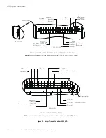
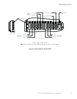
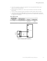
2.  Installing Parallel system, see Figure 4-10 and Figure 4-12.

3.  To locate the appropriate terminals and review the wiring and termination requirements, see 
paragraph 3.2.3, Table 4-2, Figure 4-7, Figure 4-9, and Figure 4-10.

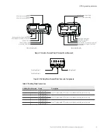
Figure 4-10. Pull Chain Terminal Block Connector Assignments

Table 4-2. Pull Chain Connections

Pull Chain Terminal 

Name

Description

1

Pull Chain +

Output:  Backup control for parallel operation.

2

Pull Chain – 

4.  Remove the small parts from the knockout in the right side plate.

5.  Route and install RJ-45 Controller Area Network (CAN) cables between the UPS cabinets. See Figure 4-7, 

Figure 4-11 and Figure 4-12 for wiring information.

Pull Chain

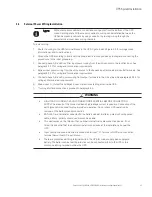
CAUTION

• 

Parallel system combined input and output cable length should be in accordance with the 

following rule. It should be designed to ensure that wiring impedance from point of supply to 

UPS input and from UPS output to load connection for each UPS module in a multi-module 

system is equal, or within a tolerance of approximately ±10%. This is to ensure approximately 

equal current sharing when in static bypass mode and restrain input/output high frequency loop 

current of parallel system. Suggest that parallel system combined input and output cable length 

no less than 10m, 5m for input and 5m for output.

         Total length of 1A =2A=3A=4A
                                      1B=2B=3B=4B
                                      1C=2C=3C=4C

• 

 If installing only two UPS modules (redundant), this requirement is no longer required as each 

UPS is capable of supporting the full bypass requirement. However, this would preclude future 

expansion.

• 

Ensure that each UPS static bypass is fed from a single common source, as is an external 

bypass switch if installed.  If each UPS is fed with a separate rectifier source, please consult 
Eaton for advice on compatibility.

Содержание 93E UPS

Страница 1: ...15 80 kVA 380 400 415V Installation and Operation Manual Eaton 93E UPS...

Страница 2: ......

Страница 3: ...ors de toute proc dure d installation et de maintenance des batteries et de l onduleur Veuillez consulter enti rement ces instructions avant de faire fonctionner l quipement et conserver ce manuel afi...

Страница 4: ......

Страница 5: ...SECTION 1 Installation 3 UPS Installation Plan and Unpacking 3 1 3 1 Creating an Installation Plan 3 1 3 2 Preparing the Site 3 1 3 2 1 Environmental and Installation Considerations 3 1 3 2 2 UPS Sys...

Страница 6: ...nsfer from Normal to Bypass Mode 6 12 6 3 4 Transfer from Bypass to Normal Mode 6 12 6 3 5 Transfer from Standard Normal Mode to HE mode 6 12 6 3 6 Transfer from HE Mode to Standard Normal Mode 6 13 6...

Страница 7: ...2 Performing Preventative Maintenance 8 2 8 2 1 DAILY Maintenance 8 2 8 2 2 MONTHLY Maintenance 8 2 8 2 3 PERIODIC Maintenance 8 3 8 2 4 ANNUAL Maintenance 8 3 8 2 5 BATTERY Maintenance 8 3 8 3 Insta...

Страница 8: ...Table of Contents iv Eaton 93E UPS 15 80 kVA 380 400 415V Installation and Operation Manual This page intentionally left blank...

Страница 9: ...erTerminal Locations 60 80 kVA 4 7 Figure 4 6 InterfaceTerminal Locations 4 8 Figure 4 7 InterfaceTerminal Detail Terminal Cover Removed 4 9 Figure 4 8 Building AlarmTerminal Block Connector Assignmen...

Страница 10: ...List of Figures vi Eaton 93E UPS 15 80 kVA 380 400 415V Installation and Operation Manual This page intentionally left blank...

Страница 11: ...for the Eaton 93E 15 80 kVA 3 18 Table 3 7 Recommended Input Circuit Breaker Ratings 3 19 Table 3 8 Recommended Bypass and Output Circuit Breaker Ratings 3 19 Table 3 9 Recommended DC input circuit b...

Страница 12: ...List of Tables viii Eaton 93E UPS 15 80 kVA 380 400 415V Installation and Operation Manual This page intentionally left blank...

Страница 13: ...ies clean consistent power that sensitive electronic equipment requires for reliable operation During brownouts blackouts and other power interruptions batteries provide emergency power to safeguard o...

Страница 14: ...ni Slot Communication Bays Two communication bays are standard equipment One to two optional Mini Slot connectivity cards can be installed in the UPS module at any time Mini Slot cards are quickly ins...

Страница 15: ...is load sharing system provides more capacity than a single UPS and can provide backup depending on the load and configuration In addition when one UPS is taken out of service for maintenance or is no...

Страница 16: ...backup power to safeguard operation during brownouts blackouts and other power interruptions The battery system is equipped with lead acid batteries 1 4 Basic System Configurations The following basic...

Страница 17: ...te centre This symbol indicates that you should not discard waste electrical or electronic equipment WEEE in the trash For proper disposal contact your local recycling reuse or hazardous waste centre...

Страница 18: ...Introduction 1 6 Eaton 93E UPS 15 80 kVA 380 400 415V Installation and Operation Manual This page intentionally left blank...

Страница 19: ...104 F Do not operate near water or excessive humidity 95 maximum The system is not intended for outdoor use As a result of the connected loads high leakage current is possible Connection to earth grou...

Страница 20: ...sonnel from dangerous voltages inside the unit Do not install or operate the UPS system close to gas or electric heat sources The operating environment should be maintained within the parameters state...

Страница 21: ...Section 1 Installation...

Страница 22: ......

Страница 23: ...rt of the sales contract for the UPS Contact an Eaton service representative in advance usually a two week notice is required to reserve a preferred startup date 3 2 Preparing the Site For the UPS sys...

Страница 24: ...627 46 100 wheel total 6 wheels 93E 20I N 0 MBS 102 225 120 264 17 38 wheel total 6 wheels 93E 20 N MBS 72 159 85 187 17 40 wheel total 4 wheels 93E 20T N MBS 220 484 233 513 37 81 wheel total 6 wheel...

Страница 25: ...No 3 3 From Right Side of Cabinet See Table No 3 3 From Left Side of Cabinet See Table No 3 3 The basic environmental requirements for operation of the UPS are AmbientTemperature Range 0 40 C 32 104 F...

Страница 26: ...380 400 400 415 415 862 93E 15U N MBS 15 kVA 380 380 400 400 415 415 862 93E 15UT N MBS 15 kVA 380 380 400 400 415 415 1306 93E 20I N 64 9Ah MBS 20 kVA 380 380 400 400 415 415 1149 93E 20I N 0 MBS 20...

Страница 27: ...ion Manual 3 5 Figure 3 1 UPS Cabinet Dimensions 93E 15 20 kVA Front and Right Side Views Dimensions are in millimetres inches 93E 15U 93E 20 93E 15UI 93E 15UT 93E 20I 93E 20T 706 27 8 500 19 69 960 3...

Страница 28: ...ation Manual Figure 3 2 UPS Cabinet Dimensions 93E 30 kVA Front and Right Side Views Dimensions are in millimetres inches 500 19 69 706 27 8 1230 48 43 500 19 69 706 27 8 1230 48 43 706 27 8 500 19 69...

Страница 29: ...on and Operation Manual 3 7 Figure 3 3 UPS Cabinet Dimensions 93E 40 kVA Front and Right Side Views Dimensions are in millimetres inches 706 27 8 500 19 69 1500 59 06 706 27 8 500 19 69 1500 59 06 93E...

Страница 30: ...n and Operation Manual Figure 3 4 UPS Cabinet Dimensions 93E 60 80 kVA Front and Right Side Views Dimensions are in millimetres inches 600 23 62 796 31 34 1876 73 9 600 23 62 796 31 34 1876 73 9 93E 6...

Страница 31: ...06 27 8 706 27 8 796 31 34 Figure 3 5 UPS Cabinet Dimensions Top and Bottom Views Dimensions are in millimetres inches FRONT FRONT FRONT FRONT FRONT FRONT TOP VIEW TOP VIEW TOP VIEW BOTTOM VIEW BOTTOM...

Страница 32: ...93E 15 20 kVA Dimensions are in millimetres inches 706 27 8 500 19 69 960 37 8 250 9 84 353 13 9 611 5 24 07 611 5 24 07 706 27 8 500 19 69 960 37 8 250 9 84 353 13 9 611 5 24 07 611 5 24 07 706 27 8...

Страница 33: ...al 3 11 Figure 3 7 UPS Cabinet Centre of Gravity 93E 30 kVA Dimensions are in millimetres inches 706 27 8 500 19 69 250 9 84 353 13 9 1230 48 43 765 30 12 765 30 12 500 706 27 8 500 19 69 250 9 84 353...

Страница 34: ...Manual Figure 3 8 UPS Cabinet Centre of Gravity 93E 40 kVA Dimensions are in millimetres inches FRONT VIEW FRONT VIEW RIGHT VIEW RIGHT VIEW 500 706 27 8 500 19 69 250 9 84 353 13 9 1500 59 06 930 36...

Страница 35: ...S Cabinet Centre of Gravity 93E 60 kVA Dimensions are in millimetres inches 600 23 62 796 31 34 1876 73 9 970 38 19 970 38 19 600 23 62 796 31 34 1876 73 9 300 11 81 300 11 81 920 36 22 920 36 22 93E...

Страница 36: ...n Manual Figure 3 10 UPS Cabinet Centre of Gravity 93E 80 kVA Dimensions are in millimetres inches FRONT VIEW FRONT VIEW RIGHT VIEW RIGHT VIEW 600 600 23 62 796 31 34 1876 73 9 300 11 81 300 11 81 102...

Страница 37: ...wiring only If wire is run in an ambient temperature greater than 30 C higher temperature wire and or larger size wire may be necessary Wire sizes are based on using the specified breakers Material an...

Страница 38: ...ice It is therefore essential that the customer install such a device at the installation site near the UPS Install a proper three pole overcurrent disconnect device before connecting to the UPS the d...

Страница 39: ...ctifier 0 99 Minimum PF Full load current plus battery recharge current 3 Phases Amps 23 31 46 61 92 123 Conductor Size Phase A B C min mm2 6 1 6 1 6 1 16 1 16 1 25 1 max mm2 6 1 10 1 25 1 25 1 50 1 7...

Страница 40: ...se A M6 bolt mounting 5 44 28 26 mm M6 M8 bolt mounting 12 106 50 24 mm M8 L2 Phase B M6 bolt mounting 5 44 28 26 mm M6 M8 bolt mounting 12 106 50 24 mm M8 L3 Phase C M6 bolt mounting 5 44 28 26 mm M6...

Страница 41: ...lations Table 3 8 Recommended Bypass and Output Circuit Breaker Ratings Circuit Breaker Rating UPS Model Load Derating 400V 93E 15 80 Derated 27A 100 Rating 22A 93E 20 80 Derated 36A 100 Rating 29A 93...

Страница 42: ...tery wiring used between the battery and the UPS should not allow a voltage drop of more than 1 of nominal DC voltage at rated battery current If the conductors used for DC input from the battery cabi...

Страница 43: ...face terminals conduit must be installed between each device and the UPS cabinet If using the power terminal wiring channel keep interface wiring separate from power wiring or use shielded wire If usi...

Страница 44: ...the packaged cabinet to the installation site or as close as possible before unpacking If possible move the cabinets using the pallet Insert the forklift or pallet jack forks between the supports on t...

Страница 45: ...5V Installation and Operation Manual 3 23 While waiting for installation protect the unpacked cabinet from moisture dust and other harmful contaminants Failure to store and protect the UPS properly ma...

Страница 46: ...UPS Installation Plan and Unpacking This page intentionally left blank 3 24 Eaton 93E UPS 15 80 kVA 380 400 415V Installation and Operation Manual...

Страница 47: ...securing the bracket to the pallet see Figure 4 1 If installing the cabinet permanently retain the shipping bracket and securing hardware for later use 3 Attach the ramp to the front of the pallet se...

Страница 48: ...a responsible manner 9 Secure the UPS cabinet in position by lowering the leveling feet until the cabinet is not resting on the casters and the cabinet is level 10 If permanently mounting the system p...

Страница 49: ...00 415V Installation and Operation Manual 4 3 Figure 4 2 Attaching the Ramp to the Pallet Pallet Ramp UPS Cabinet Figure 4 3 Rolling the Cabinet Down the Ramp UPS System Installation Figure 4 4 Rollin...

Страница 50: ...2 Check all the external battery breakers are open 3 Connect PE first 4 Connect the battery cabinet s with cables sized according to cable cross section and protective device 5 Specification to termi...

Страница 51: ...5 Connect phase A B and C power wiring from output terminals to the critical load See paragraph 3 2 2 for wiring and termination requirements 6 Mains input N Output N and Bypass input N are connected...

Страница 52: ...er Neutral N AC Output to Critical Load 93E 15U 93E 15UT 93E 20 93E 20T 93E 30 93E 30T 93E 40 93E 40T Note Connection terminals for these models are accessible from the front of the UPS cabinet REAR V...

Страница 53: ...Terminals Internal Battery Internal Battery AC Output to Critical Load AC Input to UPS Bypass AC Input to UPS Rectifier RIGHT VIEW Phase A L1 Phase B L2 Phase C L3 Phase C L3 Phase B L2 Phase A L1 Ph...

Страница 54: ...d Figure 4 7 3 Interface cables can enter the UPS via right side panel or a knockout in the top of the cabinet see Figure 4 9 4 Connect the building alarm interface wiring as shown inTable 4 1 and Fig...

Страница 55: ...by a remote dry contact closure 4 Building Alarm 2 5 Building Alarm 3 Input Programmable UPS alarm activated by a remote dry contact closure 6 Building Alarm 3 93E 60 80 kVA 93E 15 40 kVA Building Al...

Страница 56: ...tem Installation 4 10 Eaton 93E UPS 15 80 kVA 380 400 415V Installation and Operation Manual Figure 4 9 Interface Wiring Access 93E 15 40 kVA 93E 60 80 kVA Wiring Aaccess FRONT VIEW FRONT VIEW Wiring...

Страница 57: ...re 4 11 and Figure 4 12 for wiring information Pull Chain CAUTION Parallel system combined input and output cable length should be in accordance with the following rule It should be designed to ensure...

Страница 58: ...e Connections For installation and setup of an Mini Slot card contact an Eaton service representative see paragraph 1 8 To install wiring 1 If not already installed install the LAN drop 2 Route and in...

Страница 59: ...attery UPS 1 UPS 2 UPS 3 UPS 4 IN OUT IN OUT IN OUT IN OUT CAN BUS CAN BUS CAN BUS CAN BUS CN3 CN6 CN3 CN6 CN3 CN6 CN3 CN6 1 2 1 2 1 2 1 2 1 2 1 2 1 2 1 2 1 2 RJ 45 CABLE RJ 45 CABLE RJ 45 CABLE TERMI...

Страница 60: ...it doors 3 To locate the appropriate terminals and review the wiring and termination requirements see paragraph 3 2 3 Table 4 3 Figure 4 6 Figure 4 7 and Figure 4 13 Figure 4 13 REPO Terminal Block Co...

Страница 61: ...witches in parallel with the first REPO 8 If required install wiring from the REPO switch to the trip circuitry of the upstream protective devices A second contact block is provided on the REPO switch...

Страница 62: ...tive in advance usually a two week notice is required to reserve a preferred startup date 4 8 Completing the Installation Checklist The final step in installing the UPS system is completing the follow...

Страница 63: ...r conditioning equipment is installed and operating correctly The area around the installed UPS system is clean and dust free Eaton recommends that the UPS be installed on a level floor suitable for c...

Страница 64: ...hen planning the battery installation allowance must be made for adequate ventilation and heat dissipation Valve regulated cells are not completely maintenace free They must be kept clean and their co...

Страница 65: ...ATTERY TRAY 3 __ IL C T I b __ L BATTERY TRAY 4 BAT __ __ BAT RED _ TO BATlERY BREAKER FRONT BAT 1 81 Aa l BAT I Bl ACK BAT r __ _ BAT RED BAT IREDl FRONT BAT I B1 Aa 1 BAT 81 Aa BAT __ _ BAT IL RED B...

Страница 66: ...UPS System Installation 4 20 Eaton 93E UPS 15 80 kVA 380 400 415V Installation and Operation Manual Notes...

Страница 67: ...Section 2 Operation...

Страница 68: ......

Страница 69: ...Rectifier Digital Metering AC Output to Critical Load The Eaton 93E UPS is a continuous duty solid state three phase true online system that provides conditioned and uninterruptible AC power to the U...

Страница 70: ...cal load The following paragraphs describe the differences in the UPS operating modes using block diagrams to show the power flow during each mode of operation 5 2 2 Standard Normal Mode During Standa...

Страница 71: ...arge cycle is complete HE mode if selected is a normal operating mode and not an alarm condition While the UPS is in this mode the NORMAL light on the front display will illuminate Figure 5 2 Path of...

Страница 72: ...unable to support the applied load The continuous static switch is wired in series with the backfeed protection contactor if fitted and together they are wired in parallel with the rectifier and inve...

Страница 73: ...d rectifier snubber components to the utility source If the input power fails to return or is not within the acceptance windows required for normal operation the battery continues discharging until a...

Страница 74: ...in this section show the simplified internal structure of the UPS battery supply and basic maintenance bypass 5 3 Single UPS Unit System Oneline Configurations See Figure 5 5 See Tab 9 1 for Model 38...

Страница 75: ...nal Backfeed Contactor Output Switch MBS AC Output to Critical Load Battery relay Rectifier Inverter L1 L2 L3 N Pull Chain Parallel CAN Mini Slot Interface Remote EPO Fuse Fuse Battery Contactor Batte...

Страница 76: ...tional Backfeed Contactor Output Switch MBS AC Output to Critical Load Battery relay Rectifier Inverter L1 L2 L3 N Pull Chain Parallel CAN Mini Slot Interface Remote EPO Fuse Fuse Fuse Fuse disconnect...

Страница 77: ...indicators and Figure 6 2 shows the UPS switches Before starting the UPS ensure all installation tasks are complete and a preliminary startup has been performed by authorised service personnel The pr...

Страница 78: ...ctions see paragraph 6 2 Neutral Switch Neutral Switch Neutral Switch Neutral Switch Output Switch Output Switch Output Switch Output Switch Input Switch Input Switch Input Switch Input Switch Mainten...

Страница 79: ...ators These colored light emitting diode LED lamps work with the alarm horn to let you know the operating status of the UPS Table 6 1 describes the status indicators 2 1 3 Table 6 1 Status Indicators...

Страница 80: ...n see paragraph 6 2 6 System Event Horns The system event horn beeps to alert an operator that an event needing attention is taking place The horn cycles at a half second rate System Event Indicators...

Страница 81: ...e information area contains data about UPS status and operations The menu bar shows the symbols of the available screens To select a screen highlight the screen symbol using the navigation pushbuttons...

Страница 82: ...ame and meter subscripts change the password and view the firmware version numbers ESC Returns to Main Menu and Mimic screen from the Meters Events History Controls or Setup screens Returns to the mai...

Страница 83: ...screen can be used to display user information and show the firmware versions installed Use the LEFT or RIGHT arrow pushbuttons to select the SETUP symbol on the main menu bar to display the Setup scr...

Страница 84: ...rn to the System Setup screen press the ESC pushbutton Unit Name The Unit Name Setup screen allows a unit name to be entered Use the UP or DOWN arrow pushbutton to highlight Unit Name then press the R...

Страница 85: ...tton to highlight the command screen desired then press the RETURN pushbutton to display the command menu screen Use the or pushbutton to highlight the command desired Table 6 4 describes the control...

Страница 86: ...ard Normal mode Battery Control Commands Use the up or down arrow pushbutton to highlight the command function desired then press the RETURN pushbutton to execute the command Charger Turns the battery...

Страница 87: ...bypass input switch 9 If the UPS contains an output switch close the output switch 10 Make sure MBS cover is installed 11 Close the door and secure the latch 12 Close the external battery breakers 13...

Страница 88: ...se the bypass input switch 9 Close the output switch 10 Make sure MBS cover is installed 11 Close the door and secure the latch 12 Close the external battery breakers 13 Observe the UPS control panel...

Страница 89: ...nsfer the critical load to Normal mode 1 Select the CONTROLS symbol on the main menu bar The System Control screen is displayed 2 If not already selected select UPS on the System Control screen 3 On t...

Страница 90: ...ut 6 Loosen the screws that fix the cover over the Neutral switch 60 80 kVA open the Neutral switch The Neutral Switch should remain closed unless operated by a service technician Maintenance Bypass o...

Страница 91: ...the installed external battery cabinet 4 Open the UPS Input switch 5 If the UPSs are wired for dual input open the Bypass input switch 6 Open the Maintenance Bypass switch 7 Open the UPS input and byp...

Страница 92: ...ass remains off until restarted To use the LOAD OFF command 1 Select the CONTROLS symbol on the main menu bar The System Control screen is displayed 2 Select UPS on the System Control screen 3 On the...

Страница 93: ...ns are for the Eaton supplied REPO switch If a customer supplied REPO switch is used it may not activate in the same manner refer to the operating instructions provided with the switch NOTE To use the...

Страница 94: ...hes 9 Make sure MBS cover is installed 10 Close the door and secure the latch 11 Close all external battery breakers 12 Observe the UPS control panel display becoming active indicating logic power 13...

Страница 95: ...PS input feeder circuit breakers 6 If the UPSs are wired for dual input close all of the UPS Bypass input feeder circuit breakers 7 Close all input breakers 8 If the UPSs are wired for dual input clos...

Страница 96: ...e RETURN pushbutton All of the UPSs transfer to Bypass mode The BYPASS status indicator is illuminated The power module remains on WARNING Power is present inside the UPS cabinet 6 4 4 Transfer from B...

Страница 97: ...d 2 Close the UPS input and bypass feeder circuit breakers for the UPS being restarted 3 Close the input switch 4 If the UPSs are wired for dual input close the bypass input switch 5 Close the output...

Страница 98: ...tery charger off procedure in paragraph 6 4 8 for each UPS The input and battery relay open WARNING Power is present inside the UPS cabinets after the upstream input feeder circuit breakers are opened...

Страница 99: ...the critical load The UPSs including Bypass remains off until restarted To use the LOAD OFF command 1 Select the CONTROLS symbol on the main menu bar on the UPS to be shut down The System Control scre...

Страница 100: ...an emergency you can use this switch to control the UPS output The REPO switch de energises the critical load and powers down the UPS immediately without asking for verification The UPSs including Byp...

Страница 101: ...kVA 208 220V Installation and Operation Manual P 164000058 Rev 2 7 1 Chapter 7 Communication This chapter describes the communication features of the Eaton 9E UPS For terminal wiring information see p...

Страница 102: ...Communication This page intentionally left blank 7 2 Eaton 93E UPS 15 80 kVA 380 400 415V Installation and Operation Manual...

Страница 103: ...arging source prior to connecting or disconnecting terminals Determine if the battery is inadvertently grounded If it is remove the source of the ground Contact with any part of a grounded battery can...

Страница 104: ...ated If an alarm lamp is illuminated or the Normal status indicator is not illuminated contact an Eaton service representative 8 2 2 MONTHLY Maintenance Perform the following steps monthly 1 Monitor s...

Страница 105: ...nce procedures should specify that the compression lug connections be retorqued to values listed in this manual 8 2 4 ANNUAL Maintenance Annual preventive maintenance should be performed only by autho...

Страница 106: ...er le m me nombre et mod le des batteries L limination des batteries est r glement e Consulter les codes locaux cet effet Do not discard the UPS or the UPS batteries in the trash This product contains...

Страница 107: ...S 20 kVA 50 60 Hz 93E 20 N MBS 20 kVA 50 60 Hz 93E 20T N MBS 20 kVA 50 60 Hz 93E 30I N 96 9Ah MBS 30 kVA 50 60 Hz 93E 30I N 0 MBS 30 kVA 50 60 Hz 93E 30 N MBS 30 kVA 50 60 Hz 93E 30T N MBS 30 kVA 50 6...

Страница 108: ...Overload Capability 110 for 60 minutes 125 for 10 minutes 150 for 1 minutes 150 for 500 milliseconds Operating Input Voltage 380 400 415 Vac Input Voltage Range 190 330 276 478V 15 20 at 100 load 116...

Страница 109: ......

Страница 110: ...614 01802 00...

Отзывы: