Installation
Eaton
®
Power Xpert 9395 Integrated Battery Cabinet (Model 1085 and 1085HR) Installation Manual 164201687—Rev 06
www.eaton.com/powerquality
4-9
6.
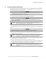
Follow the required battery cable routing instructions specified in Section 3.2.2 above. Route and connect
the other end of the battery output cables to the battery disconnect input terminals. Refer to the
applicable installation instructions for the battery disconnect for terminal locations and termination
requirements.
7.
Route and connect the battery disconnect output cables to the UPS cabinet battery input terminals E4 and
E5 and ground terminals. Refer to the applicable Power Xpert 9395 Installation and Operation manual
listed in paragraph 1.7 for UPS cabinet terminal locations and termination requirements.
8.
Repeat Steps 1 through 7 for each battery cabinet, and then proceed to paragraph 4.3.3.
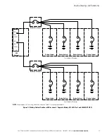
Figure 4-7. 1085 Battery Power and Interface Terminal Locations
Cabinet to UPS Negative
Terminals ( )
Cabinet to UPS Positive
Terminals (+)
Interface Terminal Block TB1
and Connectors J3 And P3
(see Figure 4
‐
11 For details)
Battery Breaker
Ground Terminal
NOTE
Use pressure and bus bar terminations as necessary for connecting cables between the UPS and battery cabinets.
Inter
‐
Cabinet Wiring Access
to Route Interface Wires
Between Cabinets
Inter
‐
Cabinet Wiring Access
to Route Interface Wires
Between Cabinets
EMP Mounting Location
(if installed)
Ground Stud
Ground Stud


