EasyStand Bantam Скачать руководство пользователя страница 23

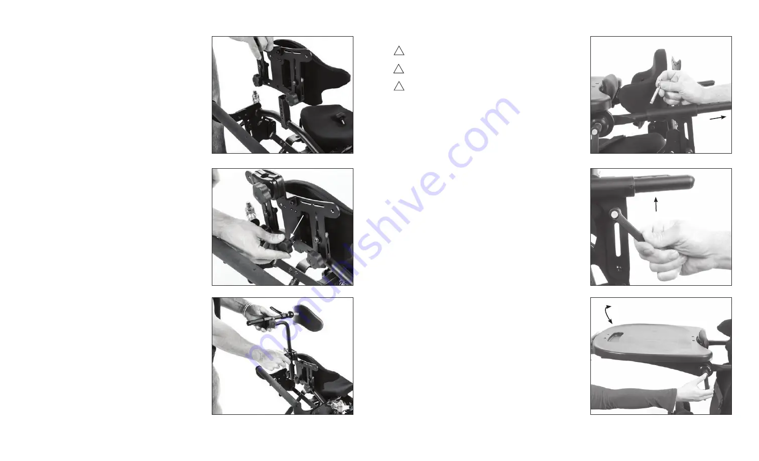
25 . If not already on the unit, remove the knob from the 

center post and place the back onto the unit as shown.

26 . Place the back in the desired position. Insert knob 

and tighten securely.

27 . If you ordered only the optional headrest, insert the 

head support onto the unit and tighten securely.

Shadow Tray Adjustment

Caution: These adjustments are only to be made while 

the unit is in the seated position.
Caution: Always support the tray when loosening the 

ratchet handles to adjust the tray.
Caution: After placing the tray into position, ensure the 

ratchet handles on the side of the tray are tightened 

securely. 
Black Molded Tray and Clear Tray Depth

48.To adjust the depth of the optional tray, place tray 

tubes into the receptacles and line up holes to the 

desired depth, and insert pins.
49 . To adjust the height of the tray, loosen both ratchet 

handles on the side of the unit and lift the tray to the 

user’s desired height, tighten securely.
50 . To adjust the angle of the tray, loosen both ratchet

handles on the side of the tray and position the tray to 

the user’s desired angle, tighten securely.

Page 11

Page  20

!

!

!

48

49

50

Содержание Bantam

Страница 1: ...vement and reserves the right to change features specifications and prices without prior notification Check with Altimate Medical for latest information FORM MBANEX SMALL 081216 REV A Copyright 2016 Altimate Medical Inc All rights reserved Printed in the U S A 262 West 1st St Morton MN 56270 USA Toll Free 800 342 8968 or 507 697 6393 Fax Free 877 342 8968 or 507 697 6900 email info easystand com e...

Страница 2: ...ns The warranty will be void if parts not manufactured by Altimate Medical or parts not complying with original equipment specifications are added to an Altimate Medical product THE FOREGOING WARRANTY IS EXCLUSIVE AND IN LIEU OF ALL OTHER EXPRESS WARRANTIES ALTIMATE MEDICAL SHALL NOT BE LIABLE FOR ANY CONSEQUENTIAL OR INCIDENTAL DAMAGES WHATSOEVER Altimate Medical maintains a policy of continual p...

Страница 3: ...hed on both sides Am I suppose to use the bolts to secure the tray in place The bolts and nuts are used as a tray depth guide You can move them to any one of the holes on the tray adjustment arm depending on the person using the unit To use remove from the tray position the tray with the correct depth and then reinstall in the hole closest to the tray top This will stop the arms at the cor rect de...

Страница 4: ...e hydraulic actuator on the EasyStand has a high probability of getting air trapped in the internal workings of the unit This is usually caused by in transit handling and is quite normal Please follow the simple steps below as manual hydraulic systems may never operate properly unless the entrapped air is correctly purged The unit must be at room temperature for this procedure 1 Pump the handle un...

Страница 5: ...horized dealer or service center Only Altimate Medical Inc approved replacement parts should be used to ensure safety and performance If the EasyStand is being used in the home environment please inspect the unit prior to each use to ensure there is no damage or unexpected wear to the EasyStand that may have been caused unintentionally by pets pests or children Never reposition the foot plates whi...

Страница 6: ...he casters to the axel as shown Line up the bolt and nut using a 17mm wrench and hex wrench tighten the nut securely 2 Remove the two bolts and two coved nuts from front frame 3 Flip up the rear frame to allow easier access to the post Attach the front and rear frames to one another Options Parts Detail Page 3 Page 28 ...

Страница 7: ...imum distance between portable and mobile RF communications equipment transmitters and the EasyStand Bantam as recommended below according to the maximum output power of the communications equipment Rated maximum output power of transmitter 150 kHz to 80 MHz 80 MHz to 800 MHz 800 MHz to 2 5 GHz Separation distance according to frequency of transmitter d 1 2 P m d 1 2 P d 2 3 P 12 12 23 38 38 73 1 ...

Страница 8: ...ended separation distance in meters m Field strengths from fixed RF transmitters as deter mined by an electromagnetic site surveya should be less than the compliance level in each frequency range b Interference may occur in the vicinity of equipment marked with the following symbol IEC 60601 Test Level Electromagnetic Environment Guidance NOTE 1 At 80 MHz and 800 MHz the higher frequency range app...

Страница 9: ...n the electromagnetic environment specified below The customer or the user of the EasyStand Bantam should assure that it is used in such an environment Immunity Test Electrostatic Discharge ESD IEC 61000 4 2 6 kV contact 8 kV air 6 kV contact 8 kV air Floors should be wood concrete or ceramic tile If floors are covered with synthetic material the rela tive humidity should be at least 30 Mains powe...

Страница 10: ...here the cords are plugged in Once the batteries have reached their end of life and need to be replaced do not open the control box please contact Altimate Medical Customer Service or your medical equipment dealer for information about purchasing a replacement control box It is recommended that the batteries be replaced every four years Please contact a local recycling authority for information ab...

Страница 11: ...ch can occur from overcharging The charger can be found in the tool pouch on the back of the unit CAUTION Use only the Linak charger model numbers 10CH01S 00 provided by Altimate Medical with the Pow r Up option 1 Plug the receptacle into a wall outlet The light on the charger will be green indicating an open circuit 2 FIG A Plug the charger cord into the side of the hand control The light on the ...

Страница 12: ...s should still be able to spin freely Plunger Handle A B 2 Washers Remove Head Support Adjustment 56 To adjust the head support height loosen the knob on the back of the back option move to desired position and tighten securely 57A To adjust the head support depth loosen the knob on the back of the headrest and slide into desired posi tion tighten securely 57B To adjust the head support angle loos...

Страница 13: ...he tray are tightened securely For the Swing Away Shadow Tray remove plastic from knobs on unit loosen knobs insert tray and tighten securely A B Swing Away Shadow Tray Adjustment Black Molded Multi Adjustable Tray Height 51 To adjust tray height loosen knobs on the side of unit and set to desired position Tighten securely Multi Adjustable Tray Depth 52 Loosen knob under the tray pull or push into...

Страница 14: ...et handles to adjust the tray Caution After placing the tray into position ensure the ratchet handles on the side of the tray are tightened securely Black Molded Tray and Clear Tray Depth 48 To adjust the depth of the optional tray place tray tubes into the receptacles and line up holes to the desired depth and insert pins 49 To adjust the height of the tray loosen both ratchet handles on the side...

Страница 15: ...ghout the possible range of elevation The now locked platform may be raised and lowered as necessary by means of the hydraulic pump or Pow r Up option however equipped 47 While accommodating the patient in the Supine mode in less than a fully extended position it must be noted that the overall range of elevation will be decreased by the inverse amount That is to say the footrest carrier will never...

Страница 16: ...ck in position Independent Drive Wheel Locks Independent Push Rim Angle Adjustments Controller Usage Neutral Mode 44 By lifting the safety collar and moving the shift knob into Neutral position the footrest carrier and backrest which are linked through the following arm now enjoy freedom of movement 45 The footrest for the safety of the user cannot exceed parallel with the seat nor can knee flexio...

Страница 17: ...together FIG D Forward Aft Loosen knobs underneath foot plates slide foot plates into position FIG E Toe in Toe out Loosen knobs underneath foot plates slide foot plates into position FIG F Abduction Loosen clamps to spread apart foot plates tighten clamps Loosen knobs under foot plates and slide foot plates apart Always tighten knobs securely FIG E Toe in Toe out FIG F Abduction Adjustments Usage...

Страница 18: ...est Vest Top Mounting Hole Chest Vest Bottom Mounting Hole Chest Vest Bottom Mounting Hole Lateral Support Slot Lateral Support Slot Hip Supports Lateral Supports Options 36 The optional hip supports can be removed for transferring The hip support width can be adjusted by loosening the knobs underneath the seat Loosen the knob on the side of the unit to adjust the hip support width Always tighten ...

Страница 19: ...est Vest Top Mounting Hole Chest Vest Bottom Mounting Hole Chest Vest Bottom Mounting Hole Lateral Support Slot Lateral Support Slot Hip Supports Lateral Supports Options 36 The optional hip supports can be removed for transferring The hip support width can be adjusted by loosening the knobs underneath the seat Loosen the knob on the side of the unit to adjust the hip support width Always tighten ...

Страница 20: ...together FIG D Forward Aft Loosen knobs underneath foot plates slide foot plates into position FIG E Toe in Toe out Loosen knobs underneath foot plates slide foot plates into position FIG F Abduction Loosen clamps to spread apart foot plates tighten clamps Loosen knobs under foot plates and slide foot plates apart Always tighten knobs securely FIG E Toe in Toe out FIG F Abduction Adjustments Usage...

Страница 21: ...ck in position Independent Drive Wheel Locks Independent Push Rim Angle Adjustments Controller Usage Neutral Mode 44 By lifting the safety collar and moving the shift knob into Neutral position the footrest carrier and backrest which are linked through the following arm now enjoy freedom of movement 45 The footrest for the safety of the user cannot exceed parallel with the seat nor can knee flexio...

Страница 22: ...ghout the possible range of elevation The now locked platform may be raised and lowered as necessary by means of the hydraulic pump or Pow r Up option however equipped 47 While accommodating the patient in the Supine mode in less than a fully extended position it must be noted that the overall range of elevation will be decreased by the inverse amount That is to say the footrest carrier will never...

Страница 23: ...et handles to adjust the tray Caution After placing the tray into position ensure the ratchet handles on the side of the tray are tightened securely Black Molded Tray and Clear Tray Depth 48 To adjust the depth of the optional tray place tray tubes into the receptacles and line up holes to the desired depth and insert pins 49 To adjust the height of the tray loosen both ratchet handles on the side...

Страница 24: ...he tray are tightened securely For the Swing Away Shadow Tray remove plastic from knobs on unit loosen knobs insert tray and tighten securely A B Swing Away Shadow Tray Adjustment Black Molded Multi Adjustable Tray Height 51 To adjust tray height loosen knobs on the side of unit and set to desired position Tighten securely Multi Adjustable Tray Depth 52 Loosen knob under the tray pull or push into...

Страница 25: ...s should still be able to spin freely Plunger Handle A B 2 Washers Remove Head Support Adjustment 56 To adjust the head support height loosen the knob on the back of the back option move to desired position and tighten securely 57A To adjust the head support depth loosen the knob on the back of the headrest and slide into desired posi tion tighten securely 57B To adjust the head support angle loos...

Страница 26: ...ch can occur from overcharging The charger can be found in the tool pouch on the back of the unit CAUTION Use only the Linak charger model numbers 10CH01S 00 provided by Altimate Medical with the Pow r Up option 1 Plug the receptacle into a wall outlet The light on the charger will be green indicating an open circuit 2 FIG A Plug the charger cord into the side of the hand control The light on the ...

Страница 27: ...here the cords are plugged in Once the batteries have reached their end of life and need to be replaced do not open the control box please contact Altimate Medical Customer Service or your medical equipment dealer for information about purchasing a replacement control box It is recommended that the batteries be replaced every four years Please contact a local recycling authority for information ab...

Страница 28: ...n the electromagnetic environment specified below The customer or the user of the EasyStand Bantam should assure that it is used in such an environment Immunity Test Electrostatic Discharge ESD IEC 61000 4 2 6 kV contact 8 kV air 6 kV contact 8 kV air Floors should be wood concrete or ceramic tile If floors are covered with synthetic material the rela tive humidity should be at least 30 Mains powe...

Страница 29: ...ended separation distance in meters m Field strengths from fixed RF transmitters as deter mined by an electromagnetic site surveya should be less than the compliance level in each frequency range b Interference may occur in the vicinity of equipment marked with the following symbol IEC 60601 Test Level Electromagnetic Environment Guidance NOTE 1 At 80 MHz and 800 MHz the higher frequency range app...

Страница 30: ...imum distance between portable and mobile RF communications equipment transmitters and the EasyStand Bantam as recommended below according to the maximum output power of the communications equipment Rated maximum output power of transmitter 150 kHz to 80 MHz 80 MHz to 800 MHz 800 MHz to 2 5 GHz Separation distance according to frequency of transmitter d 1 2 P m d 1 2 P d 2 3 P 12 12 23 38 38 73 1 ...

Страница 31: ...he casters to the axel as shown Line up the bolt and nut using a 17mm wrench and hex wrench tighten the nut securely 2 Remove the two bolts and two coved nuts from front frame 3 Flip up the rear frame to allow easier access to the post Attach the front and rear frames to one another Options Parts Detail Page 3 Page 28 ...

Страница 32: ...horized dealer or service center Only Altimate Medical Inc approved replacement parts should be used to ensure safety and performance If the EasyStand is being used in the home environment please inspect the unit prior to each use to ensure there is no damage or unexpected wear to the EasyStand that may have been caused unintentionally by pets pests or children Never reposition the foot plates whi...

Страница 33: ...e hydraulic actuator on the EasyStand has a high probability of getting air trapped in the internal workings of the unit This is usually caused by in transit handling and is quite normal Please follow the simple steps below as manual hydraulic systems may never operate properly unless the entrapped air is correctly purged The unit must be at room temperature for this procedure 1 Pump the handle un...

Страница 34: ...hed on both sides Am I suppose to use the bolts to secure the tray in place The bolts and nuts are used as a tray depth guide You can move them to any one of the holes on the tray adjustment arm depending on the person using the unit To use remove from the tray position the tray with the correct depth and then reinstall in the hole closest to the tray top This will stop the arms at the cor rect de...

Страница 35: ...ns The warranty will be void if parts not manufactured by Altimate Medical or parts not complying with original equipment specifications are added to an Altimate Medical product THE FOREGOING WARRANTY IS EXCLUSIVE AND IN LIEU OF ALL OTHER EXPRESS WARRANTIES ALTIMATE MEDICAL SHALL NOT BE LIABLE FOR ANY CONSEQUENTIAL OR INCIDENTAL DAMAGES WHATSOEVER Altimate Medical maintains a policy of continual p...

Страница 36: ...vement and reserves the right to change features specifications and prices without prior notification Check with Altimate Medical for latest information FORM MBANEX SMALL 081216 REV A Copyright 2016 Altimate Medical Inc All rights reserved Printed in the U S A 262 West 1st St Morton MN 56270 USA Toll Free 800 342 8968 or 507 697 6393 Fax Free 877 342 8968 or 507 697 6900 email info easystand com e...

Отзывы: