background image

14

easyRAID S8 

Serial ATA Disk Array Systems

 Basic

 Configurati

on – 

 Installing 

Disk

s

Installing Disks

This section describes how to install disks in the disk array system. Read “Understanding RAID” 
on page 3 to 
decide how many disks are required.

1

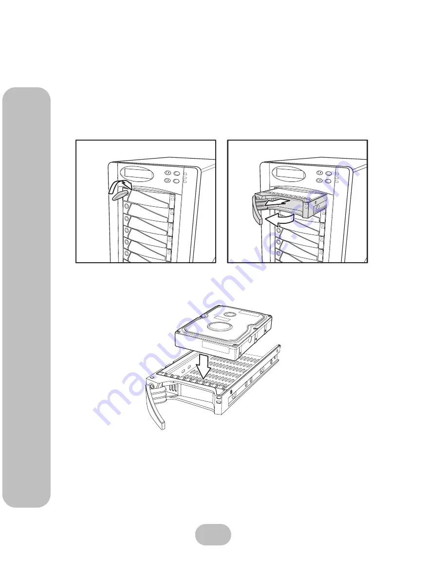
Unlock the disk tray 

(A)

 then pull the disk tray handle to the opened position 

(B)

 and 

remove the disk tray 

(C)

.

2

Insert the disk into the disk tray. The disk should face up with the connectors directed 
toward the open rear of the tray.

3

Align the back of the disk with the back of the disk tray.

ESC

Enter

ESC

Enter

A

B

C

Содержание S8-F2TT

Страница 1: ...ESC Enter easyRAID S8 U4TT Ultra 320 SCSI to Serial ATA Disk Array System easyRAID S8 F2TT Fibre Channel to Serial ATA Disk Array System Hardware User Manual ...

Страница 2: ......

Страница 3: ...tion are protected by copyright and are distributed under licenses restricting their use copying and distribution No part of this documentation may be reproduced in any form by any means without prior written authorization of the company and its licensors if any Conventions Caution This symbol is used to remind users to pay attention to important descriptions regarding usage and maintenance repair...

Страница 4: ... disk array system on an unstable cart stand or table It may fall causing serious damage to the product Keep the disk array system away from magnetic forces Do not use the disk array system near water Keep the disk array system away from dust sand or dirt Gaps and openings in the cabinet are provided for venti lation Never block or cover these openings because the disk array system may overheat an...

Страница 5: ...ject into the disk array system through cabinet gaps and openings since they may touch dangerous voltage points and cause a risk of fire or electric shock Unplug the power cord from the wall outlet before clean ing Keep the disk array system dry Do not use liquid cleaners aerosol cleaners or a wet cloth Use a damp cloth for cleaning Except as specifically explained in this User Manual do not attem...

Страница 6: ...To reduce the possibility of data errors caused by electromagnetic interference locate the disk array system at least five feet away from electrical appliances and equipment that generates magnetic fields Power Supply Safety Notes To avoid electric shocks do not use an extended power cord or an outlet that does not match the disk array system plug or leaves the plug exposed The disk array system h...

Страница 7: ... Settings 7 Host Interface 8 Hard Disks 8 Chapter 2 Basic Configuration Unpacking 9 Components 10 Front View 10 Control Panel 11 Disk Tray 12 Rear View 13 Installing Disks 14 Making Connections 16 Connecting the Host Interface 16 Connecting the RS 232 Cable 17 Connecting and Turning on the Power 18 Chapter 3 Maintenance Replacing a Disk 19 Replacing a Power Supply 20 Upgrading Memory 22 Replacing ...

Страница 8: ......

Страница 9: ... possible rate Flexible data capacity management is achieved with on line RAID expansion RAID capacity division into slices and multiple logical RAIDs Management is performed through front panel or RS 232 interfaces Features The main features of the disk array system are listed as follows Refer to the specifications table on page 29 for more detailed information Operating system independent Up to ...

Страница 10: ... the user only sees one logical disk JBOD doesn t improve data availability or access rate when compared with a single disk RAID Levels The overall arrangement of disks in RAID is called the RAID level Read this section to under stand RAID levels RAID 0 In RAID 0 data is divided into pieces and written to all disks in parallel This process is called striping because the pieces of data form a strip...

Страница 11: ...tes A RAID 0 array is not useful in the following situations Applications that make sequential requests for small amounts of data These applications spend most of their I O time waiting for disks to spin whether or not they use striped arrays Applications that make synchronous random requests for small amounts of data RAID 1 In RAID 1 data is duplicated on two or more disks to provide high access ...

Страница 12: ...od data availability The sin gle parity disk is a bottleneck on sequential writes since parity must always be written to the sin gle parity disk RAID 3 consists of two or more disks used for data and one disk used for fault tolerant data The total capacity of RAID 3 is the sum of the capacities of each data disk Add disks until the desired capacity is reached then add one more disk for fault toler...

Страница 13: ... for fault tol erence The total capacity of RAID 5 is the sum of the capacities of each data disk Add disks until the desired capacity is reached then add one more disk for fault tolerance RAID 5 is best used with applications whose data has the following characteristics The data is worth protecting but not as much as RAID 1 High read data rates Small proportion of writes to reads Hot Spare Disks ...

Страница 14: ...3 Between67 for 3 disks to 94 for 16 disks Data is divided into pieces the parity of these pieces is calcu lated and the pieces are written to separate disks in parallel with the writing of the parity to a dedi cated disk RAID 5 3 3 5 Between67 for 3 disks to 94 for 16 disks Data is divided into pieces the parity of these pieces is calcu lated and the pieces and parity are written to separate disk...

Страница 15: ... oil free environment no large magnetic fields such as those generated by a high voltage power cables and motors etc no direct sunlight a flat stable surface capable of supporting the disk array system VT100 Terminal Settings Refer to the following table for a summary of VT100 terminal settings required to communicate with the disk array system Refer to your system manual for instructions on setti...

Страница 16: ...inkage to a fibre channel switch or host computer interface card With the correct SFP transceiver and optical cable the following transmission distances can be achieved Hard Disks Supply the number of serial ATA disks needed for your application Refer to Understanding RAID on page 2 to determine the number of disks needed Note Subtract the internal cable length 60 cm from the maximum SCSI bus leng...

Страница 17: ...The disk array system is heavy Be careful when lifting and moving it easyRAID S8 F2TT Fibre Channel to Serial ATA Disk Array Sys tem Hard ware User Manual easyRAID S8 U4TT Ultra320 SCSI to Serial ATA Disk Array Sys tem ESC Enter ESC Enter Power Cables Front Panel Keys User Manual Disk Array System RS 232 Cable Active Terminator easyRAID S8 U4TT Only Ultra320 SCSI Cable easyRAID S8 U4TT Only ...

Страница 18: ... Array Systems 2 Basic Configuration Components Components Front View No Name Description 1 8 Disk trays 1 to 8 Removable hot swap disk trays 9 Control panel Displays warning operating and configuration information 1 2 3 4 5 6 7 8 9 ...

Страница 19: ...ape button Returns to the previous LCD menu without making changes 4 Power on indicator Indicates the disk array system power is on 5 Power supply fail indicator Indicates a failed power supply 6 Host computer access indicator Indicates data transfer between the disk array sys tem and the host computer 7 Down button Moves down in the LCD menus 8 Enter button Selects a menu item or confirms a choic...

Страница 20: ...crews included with the disk 2 Tray lock Prevents unauthorized removal of a disk tray Opened with the included disk tray lock key 3 Tray handle Releases the disk tray 4 Power Error indicator LED Indicates normal operation of the disk when green or an error or failure of the disk when red 5 Access indicator LED Indicates that the disk is being accessed 1 1 2 5 4 3 Front Top Left Right ...

Страница 21: ...s the power supply to be released 6 Power Supply AC In Connects to a 110 240 VAC power source 7 Power Supply Handle Allows the power supply to be removed 8 easyRAID S8 F2TT Host Port 1 Primary fibre channel Connects to the host server Found only on the easyRAID S8 F2TT 9 easyRAID S8 F2TT Host Port 2 Secondary fibre channel Connects to the host server Found only on the easyRAID S8 F2TT 10 easyRAID ...

Страница 22: ...erstanding RAID on page 3 to decide how many disks are required 1 Unlock the disk tray A then pull the disk tray handle to the opened position B and remove the disk tray C 2 Insert the disk into the disk tray The disk should face up with the connectors directed toward the open rear of the tray 3 Align the back of the disk with the back of the disk tray ESC Enter ESC Enter A B C ...

Страница 23: ...Attach the disk to the disk tray with the screws supplied by the disk supplier 5 Slide the disk tray back into the empty slot A push the disk tray handle closed B then lock the disk tray C 6 Repeat these steps until all of the required disks have been installed ESC Enter ESC Enter A B C ...

Страница 24: ...l SCSI interfaces or dual fibre channel interfaces Refer to the following sections to make host interface connections Small Computer Systems Interface The easyRAID S8 U4TT has dual Ultra320 SCSI interfaces Follow these instructions to make connections 1 Connect the active SCSI terminator to the bottom connector of the easyRAID S8 U4TT host port 2 primary SCSI channel at the rear of the disk array ...

Страница 25: ...ical or copper transceivers and cables Follow these instructions to make optical connections 1 Insert the LC Optical SFP transceiver A in to the easyRAID S8 F2TT host port 1 pri mary fibre channel at the rear of the disk array system 2 Connect the optical cable B to the LC Optical SFP transceiver A Connecting the RS 232 Cable Connect the supplied RS 232 cable to the RS 232 port at the rear of the ...

Страница 26: ...to a power supply connector at the rear of the unit 2 Connect the second power cable to the remaining power supply connector 3 Press the disk array system power switch to the ON position The disk array system auto matically begins the self test sequence Note The system is equipped with auto switching power supplies that can run on 100 to 240 VAC ...

Страница 27: ... the disk tray 4 Align the rear of the new disk with the rear of the disk tray 5 Insert the new disk into the disk tray 6 Attach the disk to the disk tray with the screws that came with the disk 7 Slide the disk tray back into the empty slot then close the disk tray handle 8 Lock the disk tray with the key Note Turn off the audible alert by pressing the Up and Down function but tons on the front p...

Страница 28: ...e also appears on the LCD panel where x refers to power supply 1 or 2 and an audible alert sounds Power supplies are hot swappable which means that they can be inserted and removed while the disk array is powered on and operating Follow these steps to replace a failed power supply 1 Identify the power supply that has failed Note Turn off the audible alert by pressing the Up and Down buttons on the...

Страница 29: ...nce Replacing a Power Supply 2 Unplug the power cable connected to the failed power supply unit 3 Push the power supply release switch A in the direction illustrated and pull the power supply handle out B at the same time 4 Remove the power supply unit A B ...

Страница 30: ...omatically locks into position when fully inserted 6 Reconnect the power cable Upgrading Memory The disk array system takes a single 200 pin PC200 DDR SDRAM SO DIMM with a maximum capacity of 1 GB Follow these instructions to upgrade the memory 1 Remove the three screws from the disk array system cover then slide the cover away from the front panel and lift it off ...

Страница 31: ...disk group controller B 3 Pull the DIMM retaining clips away from the DIMM then remove the DIMM The DIMM springs out of the socket 4 Gently push the new DIMM into the socket at 45 degrees then push the corners of the DIMM down The DIMM is secured by the DIMM socket retaining clips Note The DIMM module will fit in only one direction Do not force the DIMM into place A B ...

Страница 32: ...rading Memory 5 Replace the screws then replace the daughterboard on the disk group controller taking care to align the connectors 6 Place the top cover on the disk array system slide it shut then replace the three screws to fix the cover on the disk array system ...

Страница 33: ... panel message Fan x failure where x refers to Fan 1 or Fan 2 An audible alert also sounds Follow these instructions to replace a failed fan 1 Identify the fan that has failed Note Turn off the audible alert by pressing the Up and Down function but tons on the front panel twice simultaneously Host Port 2 Host Port 1 Fan 1 Fan 2 ...

Страница 34: ...bscrews then pull the fan enclosure out of the chassis 3 Unplug the power connector remove the screws then remove the failed fan Caution High speed rotating fan blades can cause injury Wait until both fans have stopped completely before removing either of them Host Port 1 Host Port 2 Host Port 1 Host Port 2 ...

Страница 35: ...ews removed in the previous step then insert the power connector 5 Insert the fan enclosure into the chassis then tighten the fan enclosure thumbscrews Caution The fan will begin rotating immediately after it is plugged in Keep your fingers away from the blades Host Port 1 Host Port 2 Host Port 1 Host Port 2 ...

Страница 36: ......

Страница 37: ...sk scrubbing Disk Array Functions O S independent and transparent Maximum fault tolerant capacity 2 TB 256 MB 1 GB DDR SDRAM LCD panel operation indicator Audible alarm disable alarm Optional battery backup for disk array status LED indicator on disk failures Connectors 2 x 2 Gbit Fibre Channel ports 1 x RS 232 Serial port 115200 n 8 1 1 x RJ 45 Ethernet port 10 Mbps Power Supply 300W 1 1 redundan...

Страница 38: ... ESC Enter Battery Backup Interface Yes Daughter Board Interface 1 x 64bit 66MHz and 1 x 32bit 33MHz Backplane Interface Compact PCI Disk Channel Support 8 channels Disk Number Supported 8 disks Disk Connector Type Serial ATA 1 Sequence Disk Power On Select by jumper H W power on all disks S W 4 disks at a time with 2 ms interval Temperature Sensors 4 Power Connector Type 2 x ATX Fan Connector Typ...

Отзывы: