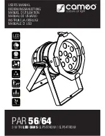
LED Light Kit Assembly Instructions for 1/2 and 1 hp Aqua Fountains
1. Attach the light fixture to the supplied brackets. The nylock nut
comes attached to the bracket for shipping. You will need to
remove nylock nut and install the yoke of the light fixture to the
bracket. Run the pig tail as shown in Figure 1. Secure the light
fixture with nylock nut.
2. Remove float cover from top of fountain. Float cover is not
secured to float and can simply be lifted off.
3. The float will have three pre-drilled holes for the light brackets.
These are marked with “LT” next to them as shown in Figure 2.
Bolt the lights, using LKH-AFBW hardware, onto the float and
tighten securely. Place the large washer on the top of the float
and run the bolt through the float.
4. To secure the light bracket to the float, line up the hole closest
to the end with the bolt. Secure bracket to bottom side of float
using nylock nut and tighten. Don’t overtighten otherwise the
upper washer may pull too far into the float. Some movement
of the bracket will not affect quality of lighting. For two light kits
swivel the light brackets to widest position possible.
5. Connect pigtails to cord splitter (two or three x 1 depending
on kit). Be sure the pigtails go around the motor screen in an
orderly way so all lights can be connected without twisting.
Verify the o-ring is present in the female portion of the
connectors. (Figure 3) Push pigtails into splitter and secure
with 1/2 turn quick connect nut on splitter. (Figure 4)
6. Connect main cord to the remaining end of the splitter section.
Be sure the o-ring is present (Figure 3) and secure cords with
1/2 turn quick connect nut. (Figure 4) Multiple cords can be
connected up to 300’ long between the light fixtures and the
control unit.
7. The main cord MUST BE SECURED to the eye bolt of the
fountain. Use the plastic cable ties included in your kit to do
this. This acts as a strain relief for the cords.
8. Adjust the angle of the light fixtures based on the spray pattern
being used. Tip in toward center for narrower pattern and tip out slightly for wider pattern.
9. Plug the main cable into the pigtail of the mounted controller unit. Be sure to mount the
weatherproof controller with timer in a secure location near a power supply and plug into 115 volt
outlet. See “Setting the Timer” for detailed instructions on the controller.
10. Over time the LED lights may appear dimmer than when new. This is caused by algae or sediment
on light lens. This can easily be removed with a small brush (a toothbrush works great).
Actual light fixture appearance may vary slightly from figures below.
3
Figure 4
Figure 1
Figure 2
Figure 3
o-ring


