background image

EASTMAN

6

Discard used sharp knives with care.

Whenever  servicing machine;  check tight-

ness of Plate  Bolt  Nut before resuming 

cutting operation.

ALL  SPECIAL  TOOLS FOR SHARPENER ADJUSTMENT CAN 

BE  OBTAINED  BY ORDERING TOOL KIT #820C2.

BEVEL-BLOC

Sharpener Shoes

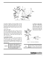
TO CHANGE THE KNIFE

Make sure sharpener is in locked position.  Raise pressure foot 

to top position by means of pressure foot lever B, located next 

to machine operating handle.   Lay machine on table as shown.  

Press in  turning knob A and turn knife to bottom position.   Insert 

T-handle  knife  bolt wrench V as shown and loosen  knife  lockbolt .   

Remove knife through bottom of standard W.  After removing knife,  

clean  knife  slot  in standard with  slot  cleaner.  Insert new knife 

in knife slot.   Be sure to set knife tightly up against  knife lockbolt 

and at the same time hold the bottom  of the  knife  against  the 

back of the slot in  the  standard  when tightening  knife  lockbolt.   

After tightening  knife  lockbolt, check to see if knife runs freely 

in standard by rotating turning knob.  Install new sharpener belts 

and operate sharpener three or four times before starting to cut.

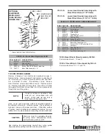
TO ADJUST BEVEL BLOC SHOES

Eastman’s  exclusive  patented  adjustable  Bevel-Bloc  sharpener 

shoes  make it possible to grind any desired bevel on  the  knife 

edge.  The knife edge bevel on your new machine is factory set 

to handle all normal fabrics and should not be changed.  Normally 

an acceptable bevel is 1/16" wide.  If necessary to adjust the 

bevel on the knife edge to a different length proceed as follows:

WARNING:

CAUTION:

®

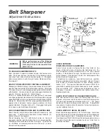
CHANGING THE KNIFE

1.  Make sure the sharpener is in the locked position.

2.  Raise the pressure foot (X) to the top position using 

the pressure foot lever (R), which is located next to the 

machine operating handle.

3.  Lay the machine on a table, as shown.

4.  Press in the turning knob (H on page 4) and turn the 

knife to the bottom position.

5.  Insert the T-handle knife bolt wrench (Y) and loosen 

the knife lockbolt (1).

6.  Remove the knife through the bottom of the standard 

(Z).

1  knife lockbolt   

R  pressure foot lever

2  slot cleaner  


X  pressure foot

E  lever   


Y  T-handle knife bolt wrench

      Z standard

7.  After removing the knife, clean the knife slot in the 

standard with the slot cleaner (2).

8.  Insert a new knife in the knife slot.  Be sure to set the 

knife tightly against the knife lockbolt. Hold the bottom 

of the knife against the back of the slot in the standard 

and tighten the knife lockbolt.

R

E

Y

1

X

Z

2

Содержание BRUTE 627VS

Страница 1: ...cify machine class no and name For electrical components also include Voltage Hertz R P M from label of your machine Some parts in this manual are covered by the following U S patents Patent No 4609244 Patent No 3714742 Patent No 3775913 Patent No 3960244 CAUTION Machine Equipped With Sharp Blade VARIABLE SPEED INTRUCTION BOOK AND PARTS LIST ...

Страница 2: ...locked position Proceed as follows Check to see that motor switch is in off position Connect attachment plug to terminal block on machine With left hand straddle front of sharpener with fingers and thumb Press in release lever N to dis engage sharpener mechanism from motor With right hand turn on motor switch allow motor to gather full speed and then release lever N This will automatically return ...

Страница 3: ... machine be modified without prior factory approval or used in such a manner that the operator does not have continuous control over the cutting machine CARE OF MACHINE Use air hose or bellows with proper eye shields and blow lint our of motor and sharpener twice a week Remove cover O and clean out lint around screw mechanism in sharpener once a week Remove knife and clean knife slides with slot c...

Страница 4: ...ws A from brush cover B Remove brush cover and gasket Remove 4 screws C from speed control cover Carefully move aside speed control cover and gasket Movement of parts will be restricted by wires but have adequate length to work without disconnecting Loosen screw E and remove the motor brush terminal only from under the fastener Remove brush retainer F by pushing in and forward to release and remov...

Страница 5: ...hold shoe from moving in If it fails to do so serrations on clamping arm are worn or shoe 11 is worn Parts should be replaced CHECK EXTREME DOWN POSITION OF SHARPENER Correct down position is having the tip of the knife at the center of the belt on shoe 12 when the belt carrier is in the most downward position and the knife is in the most upward position If the belts are too high the bottom point ...

Страница 6: ...t TO ADJUST BEVEL BLOC SHOES Eastman s exclusive patented adjustable Bevel Bloc sharpener shoes make it possible to grind any desired bevel on the knife edge The knife edge bevel on your new machine is factory set to handle all normal fabrics and should not be changed Normally an acceptable bevel is 1 16 wide If necessary to adjust the bevel on the knife edge to a different length proceed as follo...

Страница 7: ...t through the top of the guides Items Sold In Pairs With Kits Only 715C1 16 Lower Gear Bracket Assembly with Bevel Bloc Shoes 5 10 Knife 715C1 18 Lower Gear Bracket Assembly with Bevel Bloc Shoes 111 2 13 Knife 743C3 Bevel Bloc Shoe Assembly Kit R H Parts Include Items 6 10 and 11 743C3 1 Bevel Bloc Shoe Assembly Kit L H Parts Include Items 12 13 11 and 15 820C1 39 Bevel Bloc Replacment Kit 2 20C6...

Страница 8: ...UM BELT MEDIUM EDGE Shears thru the general run of rayons cottons light woolens tropicals suitings and similar materials GREEN 181C2 2 FINE BELT FINE EDGE Since thru synthetics and blends for knitted or loosely woven cloths and for silks high pile fabrics quilting etc BLUE 181C2 5 EASTMAN S FOUR ABRASIVE BELT GRITS OFFER AN EDGE FOR EVERY FABRIC For increased cutting efficiency Eastman offers four...

Страница 9: ...mmend the use of additional guarding implements However at the request of cus tomers only a lucite guard can be made available as shown in the following illustration STRAIGHT KNIFE SELECTION CHART CARBON STEEL HIGH SPEED STEEL SPECIAL PROCESS Knife STRAIGHT SAW WAVE STRAIGHT ROUND ANGLE SAW WAVE STRAIGHT Size FRONT TOOTH EDGE FRONT TIP TIP TOOTH EDGE FRONT 5 80C5 80C5 14 80C5 19 80C5HS 80C5HS R 80...

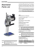
Страница 10: ... have been divided into major assemblies as follows MOTOR ASSEMBLY See pages 12 and 13 FRONT BEARING HOUSING ASSEMBLY See pages 14 and 15 SHARPENER HOUSING ASSEMBLY Front View see pages 16 and 17 Rear View see pages 18 and 19 LOWER GEAR BRACKET ASSEMBLY See pages 20 and 21 Four different abrasive belt grits designed to provide you with a selection of edges may be ordered for this machine See page ...

Страница 11: ...11 ...

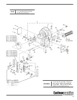
Страница 12: ... 16 190C1 14 Armature 180V 1 17 614C1 32 Motor Fan 1 18 29C6 165 Motor Adaptor STD 1 29C6 176 Motor Adaptor Micro Fog Only 1 19 536C1 71 Front Bearing Housing Assy 1 20 308C15 5 Screw 10 32 x 3 4 Socket Hd 4 21 12C1 49 Washer Lock 4 22 20C12 175 Screw Adapter 4 23 22C1 40 Handle Carring 1 24 300C14 6 Screw 10 32 x 5 8 Round Head 2 25 305C10 1 Screw 6 32 x 1 4 Grounding 1 26 12C1 32 Washer Lock 1 2...

Страница 13: ...Wire TERMINAL BLOCK Refer to Back Cover For detailed Parts List 27 29 30 32 33 31 34 35 36 37 38 8 4 45 44 43 42 45 43 44 41 40 39 2 110 90V 3 220 90V 15 90V 16 180V 28 WARNING Terminal Block must be grounded Attach ground wire to ground terminal E on ter minal Block ...

Страница 14: ...0 191C1 38 1 8 dia x 3 8 Long Wicking 1 41 17C4 6 Wrist Pin 1 42 12C1 24 Washer Lock 1 43 24C1 3 Knife Lock Bolt 1 44 4C3 8 Nut Guide Adjustment 3 45 308C12 1 Screw 8 32 x 3 8 Socket Head Cap 3 46 52C5 237 Switch Plate 1 47 580C1 198 Switch 1 48 305C8 1 Screw 4 40 X 1 4 Binding Head 3 49 4C1 111 Lock Nut 1 50 531C1 76 Cushion Grip Handle 1 51 531C1 53 Solid Handle optional 1 52 20C12 171 Screw But...

Страница 15: ...TE L H indicates left hand thread All other are right hand WARNING Switch must be grounded Slip large wire lug over switch before replacing Switch Base Secure Switch to Base Tightly to insure positive ground ...

Страница 16: ...55C4 49 Spacer 1 25 20C12 113 Screw Latch 1 26 34C10 107 Spring Latch 1 27 97C3 35 Latch Cam 1 28 309C15 7 Setscrew 1 29 621C1 7 Release Lever With Cam 1 30 12C15 57 Spring Washer 1 31 20C12 156 Screw Release Lever 1 32 300C10 1 Screw 6 32 x 3 16 Round Head 2 33 22C3 2 Lift Handle 1 34 605C1 36 Knife Guard Rod 6 8 Knife 1 35 605C1 37 Knife Guard Rod 9 10 Knife 1 36 605C1 33 Knife Guard Rod 11 1 2 ...

Страница 17: ... 12 27 20 21 22 23 25 26 28 24 19 18 17 51 50 49 48 47 46 45 39 42 44 43 41 39 38 For Spacer Chart See Sharpener Housing Assembly Rear View Page 19 5 8 Knife 9 10 Knife 11 1 2 Knife 13 Knife 6 7 8 9 34 35 36 37 5 8 Knife 9 10 Knife 11 1 2 Knife 13 Knife 13 14 15 16 5 8 Knife 9 10 Knife 11 1 2 Knife 13 Knife ...

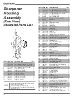
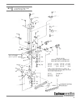
Страница 18: ... Shaft Bearing 1 28 17C15 103 Roll Pin 1 29 79C12 163 Bottom Plate 1 30 302C12 3 Screw 8 32 x 3 8 Flat Head 3 31 727C1 6 Oil Pad Holder 1 32 300C10 1 Screw 6 32 x 3 16 Round Head 2 33 302C10 6 Screw 6 32 x 1 2 Flat Head 1 34 17C15 113 Spreader Pin 1 35 716C1 12 Driver Shaft With Gear 1 36 90C4 29 Bearing Lower 1 37 90C4 42 Bearing Drive Shaft 1 38 12C15 29 Thrust Washer 2 39 87C3 8 Spiral Gear 1 4...

Страница 19: ... Knife 15 11 1 2 Knife 16 13 Knife NOTE L H indicates left hand thread All other are right hand SPACER CHART For Automatic Sharpeners See Page 17 STROKE KNIFE SPACER SPACER SIZE NUMBER LENGTH 1 1 8 1 1 4 5 73C7 55 3 7 8 1 1 2 1 3 4 5 73C7 56 4 1 4 1 1 8 1 1 4 6 73C7 57 2 7 8 1 1 2 1 3 4 6 73C7 58 3 1 4 1 1 8 1 1 4 7 73C7 59 1 7 8 1 1 2 1 3 4 7 73C7 60 2 1 4 1 1 8 1 1 4 8 1C13 12 15 16 1 1 2 1 3 4 ...

Страница 20: ...C1 5 Stabilizer 2 14 87C5 13 Intermediate Gear 1 15 4C2 63 Nut 2 16 301C7 2 Screw 4 36 X 3 16 Filister Head 2 17 Not Used 18 79C12 219 Wear Plate 2 19 34C10 45 Spring 2 20 712C1 1 L H Slide With Pulley 1 21 820C1 8 Shoe Assembly R H 1 22 12C15 93 Washer 2 23 743C1 28 Pre Set Shoe R H 1 24 21C14 14 Bushing 1 25 34C10 149 R H Sharpener Shoe Spring 1 26 20C12 153 Screw 2 27 87C3 50 Screw Shaft Gear 1...

Страница 21: ...g 20C12 57 Screw 20C12 57 Screw WHEN USING THESE SPECIAL SHOES THE FOLLOWING PARTS MUST BE REMOVED FROM THE LOWER GEAR BRACKET 35C7 28 Clamping Arm 34C10 123 Spring 20C12 143 Screw 8 4 3 5 L H 6 7 1 2 9 10 11 12 13 12 13 27 28 29 32 33 34 35 36 37 11 38 11 39 42 49 43 39 44 50 45 48 11 26 48 25 47 22 24 23 46 22 37 FOR BELT LISTING SEE PAGE 7 21 19 20 18 19 20 16 15 14 30 5 10 Knife 31 11 1 2 13 K...

Страница 22: ...red Relieved Throat Plate Assy 1 14 302C12 3 Screw 8 32 x 3 8 Flat Head 2 15 17C1 4 Pin 2 16 643C1 44 Knife Slides w screws 5 1 17 643C1 41 Knife Slides w screws 6 1 18 643C1 42 Knife Slides w screws 7 1 19 643C1 43 Knife Slides w screws 8 1 20 643C1 46 Knife Slides w screws 9 1 21 643C1 47 Knife Slides w screws 10 1 22 643C1 53 Knife Slides w screws 11 1 2 1 23 643C1 45 Knife Slides w screws 13 1...

Страница 23: ...nstall new plate roller shell reverse above procedure with base plate inverted 3 5 Standard 4 6 Standard 5 7 Standard 6 8 Standard 7 9 Standard 8 10 Standard 9 11 1 2 Standard 10 13 Standard 16 5 Knife 17 6 Knife 18 7 Knife 19 8 Knife 20 9 Knife 21 10 Knife 22 11 1 2 Knife 23 13 Knife 24 6 Micro Fog 37 Small Plate 38 Large Plate 35 34 28 31 29 Wide 30 Std 32 Small Plate for 5 8 Knives 33 Large Pla...

Страница 24: ...EASTMAN 24 ...

Страница 25: ...25 ...

Страница 26: ...EASTMAN 26 Notes ...

Страница 27: ...27 Service Record Machine Serial No Machine Voltage Date of Purchase Date Type of Service Performed ...

Страница 28: ... 51C1 63 51C1 64 51C1 65 51C1 66 51C1 67 3 20C13 103 U Lock Screw 4 4 3 3 3 4 667C1 22 Terminal Contact w Pin E 1 1 1 1 1 5 667C1 23 Terminal Contact w pin L1 N 1 1 1 6 667C1 24 Terminal Contact w Pin L2 1 1 1 7 667C1 25 Terminal Contact w Pin L3 1 1 8 51C1 61 Terminal Block Bottom 1 1 1 1 1 9 667C1 26 Terminal Contact w Pin L1 N 1 1 10 667C1 27 Terminal Contact w Pin L2 1 11 667C1 28 Terminal Con...

Отзывы: