


17
⑥
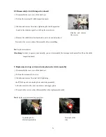
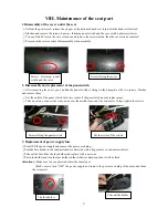
If the PCB fails, cut the wires and cable ties tightening the wires, then
replace a new one. Then connect the wires and secure it with line insulators.
⑦
Proceed in the reverse order of disassembly when assembly.
Tool:
a plus screwdriver
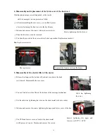
6. Disassembly of mechanical main unit
Attention:
This method can be applied when the rolling motor is OK.
If the rolling motor fails, you can refer to
7.2
mentioned below.
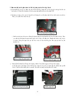
①
Slacken and remove the screw bolts, 8 pieces, fixing the cross beam
on the guide rails with a plus screwdriver.
②
Cut the cable ties around the box of electric filter, find the wires
of the kneading motor, rolling motor and height inspection,
remove the line insulators with nipper pliers, disconnect the wires.
Bear in mind the connection of the wires to avoid confusion.
( The wires with blue sleeve is connecting to kneading motor,
and the red to rolling motor)
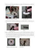
③
Pull out the terminal of the width inspection, cut the cable ties
tightening the wire. Cut the wire leading to the electric filter with wire cutters.
④
Find the wires of the rolling motor, connect to the wiring terminal of
24VDC (a little lower can be accepted) power supply. Turn on the power
to elevate the mechanical main unit, until it runs out of the guide rails.
⑤
Then you can do what you want to the mechanical main unit.
⑥
Proceed in the reverse order of disassembly when assembly.
Tools:
a plus screwdriver, nipper pliers, wire cutters,
24VDC power supply
Screw bolts fixing the cross
beam
The cross beam is removed
Close-end
The PCB and lower cover are fixed
to the sheet-metal
Содержание EC-570
Страница 40: ...39 X Electrical wiring diagram ...
Страница 41: ...40 XI Schematic diagram of the main PCB ...


