background image

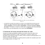
Figure 6.1

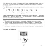
1) Pulse      (ON/OFF), el indicador de funcionamiento "  " del mando por cable se 

iluminará, y el icono de la unidad interior "      " comenzará a girar en el display, para 

indicar que la unidad interior se ha puesto en marcha. (ver Figura 6.1)

2) Pulse     (ON/OFF), el indicador de funcionamiento "  " del mando por cable se apagará 

y el icono "      " del display dejará de girar cuando la unidad se detenga.

4-2 Mod

o

Figur

a

 6.2

Pulse el botón     

 (Mod

o

).

 Con cada pulsación de este botón, el modo de funcionamiento 

cambiará según la secuencia mostrada en la Figura 6.3.

14

V.2

Содержание ECRP86EKD

Страница 1: ...RP86EKD MANUAL DE INSTRUCCIONES OPERATING MANUAL Escaneeparaverestemanualenotrosidiomasyactualizaciones Scanformanualinotherlanguagesandfurtherupdates Manuel dans d autres langues et mis jour Manual e...

Страница 2: ...V 2...

Страница 3: ...entender la informaci n que facilita antes de intentar utilizar el producto Conserve el manual para futuras consultas Si otro usuario va a utilizar este producto en el futuro aseg rese de entregarle...

Страница 4: ...9 1 Precauciones de seguridad 9 2 Componentes del mando con cable 11 3 Iconos en pantalla 13 4 Gu a de funcionamiento 13 Ajustes 24 1 Restaurar valores predeterminados 24 2 Configuraci n y consulta di...

Страница 5: ...ento para futuras consultas La instalaci n debe ser llevada a cabo por su distribuidor o por personal autorizado No intente instalar el mando de control con cable usted mismo Consulte a su distribuido...

Страница 6: ...os Aseg rese de que el cableado est bien sujeto de que se utilicen los cables especificados y de que no haya tensi n en las conexiones de los terminales o en los cables Las conexiones inadecuadas o la...

Страница 7: ...a grande Tornillo de cabeza plana peque o Caja de control el ctrico de dimensiones espec ficas para empotrar en pared 2 AWG16 AWG20 preparados para empotrar en pared La longitud m xima de los cables e...

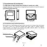
Страница 8: ...direcci n de rotaci n para evitar cualquier da o a la cubierta posterior del mando con cable ver Figura 3 3 3 Procedimiento de instalaci n 3 1 Determine el lugar donde desea instalar el mando con cabl...

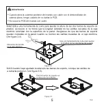
Страница 9: ...la caja el ctrica Ver figura 3 4 3 3 3 Cuando haya ajustado la altura de las barras de soporte coloque las varillas de la cubierta posterior Ver figura 3 5 Ubicaci n del tornillo en la caja el ctrica...

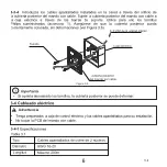
Страница 10: ...ilice para ello los tornillos Philips suministrados accesorio 1 Aseg rese de que la cubierta posterior queda correctamente colocada sin deformaciones ver Figura 3 6 Si aprieta demasiado los tornillos...

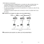
Страница 11: ...Los par metros mostrados en el mando con cable se actualizan en tiempo real de acuerdo con los cambios en los par metros de la unidad interior X1 y X2 son terminales para conectar la unidad interior y...

Страница 12: ...mandos con cable a una sola unidad interior No permitido 2 a 1 1 a 1 2 a 1 3 5 Instalaci n del cuerpo principal del mando con cable Introduzca los cables apantallados instalados en la pared a trav s d...

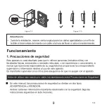
Страница 13: ...s en todo momento Figura 3 10 Advertencia Funcionamiento 1 Precauciones de seguridad Este aparato no est dise ado para que lo utilicen personas incluidos ni os con facultades f sicas sensoriales o men...

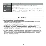
Страница 14: ...proveedor No modifique ni repare el mando con cable Esto puede provocar descargas el ctricas o incendios Consulte con su proveedor No cambie de ubicaci n ni reinstale el mando con cable usted mismo U...

Страница 15: ...descargas el ctricas no maneje el dispositivo con las manos mojadas No lave el mando por cable con agua De lo contrario podr a sufrir descargas el ctricas o provocar un incendio No coloque el mando co...

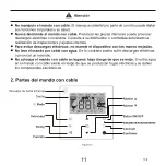
Страница 16: ...or Ajusta el movimiento de las lamas Pulse este bot n para apagar el temporizador el LED de la unidad interior el modo Silencio el modo ECO la resistencia auxiliar o para cancelar el temporizador Puls...

Страница 17: ...namiento Funci n de bloqueo Timer ON OFF Velocidad del ventilador Swing Funci n Transmisi n de se al Temperatura 13 comenzar a girar cuando la unidad Nota 1 Cuando la unidad interior se encienda el ic...

Страница 18: ...r que la unidad interior se ha puesto en marcha ver Figura 6 1 2 Pulse ON OFF el indicador de funcionamiento del mando por cable se apagar y el icono del display dejar de girar cuando la unidad se det...

Страница 19: ...4 Auto Cool Heat Dry Fan El modo Auto y Dry no est n disponibles para todos los modelos de aire acondicionado En el modo Auto pulse y los iconos Cool y Heat parpadear n Pulse para ajustar las temperat...

Страница 20: ...le viene configurado con 3 velocidades pulse Velocidad para ajustar la velocidad seg n la Figura 6 7 En los modos Auto y Dry la velocidad del ventilador se configura en Auto y no cambiar aunque se pul...

Страница 21: ...ento de las lamas verticales de la unidad interior ver Figura 6 8 Cuando la unidad est encendida la pantalla muestra el ngulo de oscilaci n actual de las lamas Pulse Swing para cambiar el ngulo de abe...

Страница 22: ...or aparecer en pantalla A continuaci n pulse el bot n para confirmar el icono se iluminar en pantalla para cancelar pulse el bot n el icono de la funci n Indicador LED de unidad interior desaparecer d...

Страница 23: ...tivada Activar desactivar la funci n Silencio pulse el bot n para ir a la funci n Silencio el icono parpadear en pantalla a continuaci n pulse para confirmar y activar la funci n o bien pulse para can...

Страница 24: ...ctivar la funci n o bien pulse para cancelar y desactivar la funci n ver Figura 6 14 Cuando cambie el modo de funcionamiento o apague la unidad el sistema cancelar la funci n ECO autom ticamente Trans...

Страница 25: ...utiliza para programar el encendido apagado de la unidad interior Cuando las funciones Follow Me del mando con cable y del mando a distancia est n activas al mismo tiempo la funci n Follow Me del mand...

Страница 26: ...ar a la pantalla de ajustes del temporizador para cancelar el temporizador pulse o el bot n de encendido apagado o introduzca el valor 0 Vuelva a la p gina de inicio Cuando la unidad est encendida el...

Страница 27: ...es el mando de control centralizado el que bloquea el rango de temperatura el icono y el marco se iluminar n en la pantalla al mismo tiempo Cuando la orden de bloqueo la emitan ambos mandos de control...

Страница 28: ...tado Ajustes de campo para determinar cu l de los mandos ser el principal y cual el secundario Por defecto el mando por cable viene configurado como mando principal Nota 4 8 Mando por cable principal...

Страница 29: ...Pulse para salir de la p gina de ajustes La funci n Configuraci n y consulta de la direcci n de la unidad interior est disponible en la pantalla de configuraci n de direcci n de red Al acceder a dich...

Страница 30: ...o de puesta en marcha est abierta el mando con cable no responder a las se ales del mando a distancia Cuando la p gina de configuraci n del par metro de puesta en marcha est activada las funciones de...

Страница 31: ...h Configuraci n del sensor de infrarrojos del mando por cable 00 Disable 01 Si selecciona Disable desactivar el mando por cable no podr recibir la se al de control remoto 01 Enable Selecci n de veloci...

Страница 32: ...cos de presi n est tica consulte la unidad interior FF el valor inicial se basa en los datos de la unidad interior que lee el mando por cable C101 Ajusta el tiempo de retardo para detener el ventilado...

Страница 33: ...ste de la resistencia aux ud interior 00 Ninguna Ud interior com n 01 FAPU 00 01 Disponible C151 Ajuste de autorreinicio de la ud interior 00 Ninguna 01 01 Disponible C165 Ajuste de swing vertical de...

Страница 34: ...n Follow Me Celsius 5 0 5 0 C Fahrenheit 9 0 9 0 F Celsius 3 0 C Fahrenheit 6 0 F Precisi n de 0 5 C 1 F C21 Determinala temperatura ambienteexterior cuandoel calentadorauxiliar est encendido Celsius...

Страница 35: ...enheit 86 F 62 F Solo disponible en el mando por cable C27 Ajusta el valor en pantalla a 0 5 C 00 01 00 00 Muestra1 C 01 Muestra 0 5 C Celsius 17 C 20 C Fahrenheit 62 F Celsius 30 C Fahrenheit 86 F So...

Страница 36: ...0 00 inv lido 01 v lido Ajuste de capacidad 0 Inv lido 0 1 19 9HP 0 1HP puede configurar 21 40HP 1HP puede configurar La unidad interior no puede cambiar el ajuste de capacidad cuando recibe 0 C31 De...

Страница 37: ...Pa 280 Pa 290 Pa 300 Pa 310 Pa 320 Pa 330 Pa 340 Pa 360 Pa 380 Pa 400 Pa 5 Este par metro no est disponible para los modelos FAPU 3 S lo para conductos de alta presi n est tica Capacidad 00 01 02 03 0...

Страница 38: ...sultar par metro n aparece en la zona de la pantalla reservada para los datos del temporizador en la parte superior de la p gina de consulta la descripci n del par metro consultado aparece en la zona...

Страница 39: ...scarga del compresor B 7 Corriente A del compresor Inverter A 8 Corriente A del compresor Inverter B 9 Reservado 10 Velocidad del ventilador 11 Posici n A de la VEE 4 12 Posici n B de la VEE 4 13 Posi...

Страница 40: ...de placas T6B 24 Temperatura C de la entrada del intercambiador de placas T6A 25 Grado de sobrecalentamiento de descarga del sistema 26 27 N de unidades interiores operativas en el caso de direcciones...

Страница 41: ...d HP de la ud interior 3 Direcci n de red de la ud interior igual que direcci n de comunicaci n 4 Temperatura de consigna Ts 5 Temperatura ambiente T1 6 Temperatura real T2 interior 7 Temperatura real...

Страница 42: ...1 5 C digos de error Listado de c digos de error de la unidad interior Error Code C digo de error y descripci n FE La unidad interior no tiene direcci n E0 Conflicto entre los modos de funcionamiento...

Страница 43: ...resi n E7 Fallo del sensor de temperatura de descarga P2 Protecci n contra baja presi n E8 Errordeladirecci ndelaudexterior XP3 Protecci ncontrasobrecorrientedelcompresor XE9 Fallo de desajuste del ac...

Страница 44: ...allo de disminuci n de la cantidad de uds interiores XL3 Reservado H8 Error del sensor de alta presi n XL4 Fallo MCE sincronizaci n ciclo cerrado H9 Fallo protecci n P9 x 3 veces en 60 minutos XL5 Pro...

Страница 45: ...tropeado Sustituya el mando con cable Algunasfuncionesdela unidadinteriornosepueden controlar comoel encendido apagado la temperatura elmodode funcionamiento lavelocidad delventiladoryelbloqueo delman...

Страница 46: ...erstand the information before attempting to use the controller Keep this manual where it is readily accessible after reading it through If another user operates the controller in the future be sure t...

Страница 47: ...9 1 Safety Precautions 9 2 Parts of the Wired Controller 11 3 Icons in the Display 13 4 Operation Guide 13 Field Setting 24 1 Restore Factory Default 24 2 Query and Set the Indoor Unit Address 25 3 C...

Страница 48: ...installation work Do not attempt to install the wired controller yourself Improper installation may result in leakage electric shocks or fire Consult your local dealer regarding relocation and reinsta...

Страница 49: ...in electric shock and or fire Make sure that all wiring is secured the specified wires are used and that there is no strain on the terminal connections or wires Improper connections or securing of wir...

Страница 50: ...copper wires Wiring tubes insulation suite Big Phillips screwdriver Small slotted screwdriver General specification for electrical box which is embedded into the wall 2 AWG16 AWG20 pre embedded into w...

Страница 51: ...ndicated to remove the rear cover of the wired controller Pay attention to the direction of rotation to prevent any damage to the rear cover of the wired controller see Figure 3 3 3 3 Rear Cover Insta...

Страница 52: ...see Figure 3 4 3 3 3 Once the heights of the plastic support bars are adjusted fix the bars on the rear cover see Figure 3 5 Screw post of electrical box Fix the support bars in the direction of the...

Страница 53: ...e rear cover of the wired controller to the electrical box via the support bars Make sure that the rear cover is not deformed after being installed see Figure 3 6 3 4 1 Wiring specification The rear c...

Страница 54: ...e indoor unit and wired controller is bi directional communication The parameters displayed on the wired controller are refreshed in real time according to changes in the parameters of the indoor unit...

Страница 55: ...ndoor unit connection method Not allowed 2 to 1 1 to 1 2 to 1 3 5 Install Main Body of Wired Controller Take the shielded wiring that has been pre embedded in the wall and pass it through the wiring h...

Страница 56: ...elow This controller is not intended to be used by persons including children with reduced physical sensory or mental capabilities or lack of experience and knowledge unless they are supervised or hav...

Страница 57: ...in electric shocks or fire Consult your dealer Do not modify or repair the wired controller This may result in electric shocks or fire Consult your dealer Do not relocate or reinstall the wired contro...

Страница 58: ...electric shocks do not operate with wet hands Do not wash the wired controller Doing so may cause electric leakage and result in electric shocks or fire Do not leave the wired controller wherever ther...

Страница 59: ...that can be set in the current mode To set the fan speed To set the swing function To turn off the timer IDU LED display silent ECO auxiliary heater function1 to cancel the timer To turn on the timer...

Страница 60: ...nder indicator Indoor unit ON OFF1 Operating mode Lock indicator Timer ON OFF Fan speed Swing Function Signal transmission indicator Temperature 13 4 1 ON OFF Setting Note1 When the indoor unit is on...

Страница 61: ...spin to indicate that the indoor unit has started running see Figure 6 1 2 Press ON OFF button again and the Operating Indicator on the wired controller will turn off and the display icon will stop sp...

Страница 62: ...Figure 6 4 Auto Cool Heat Dry Fan The Auto mode is not available for all air conditioner models In the Auto mode press and buttons Cool and Heat button blink Press to set cool and heat setpoint tempe...

Страница 63: ...e wired controller is configured with three fan speeds press Fan speed button to set the fan speed in turn as shown in Figure 6 7 In the Auto and Dry modes the fan speed is set to Auto and will not ch...

Страница 64: ...ntrol the swing of the vertical louver of indoor unit see Figure 6 8 When the unit is on the display icon shows the swing angle of the current louver Press Swing button and the louver switches from th...

Страница 65: ...he selected function see Figure 6 11 Press Function button to switch to the function that can be set in the current mode see Figure 6 10 Press Function button to go to the function setting page Press...

Страница 66: ...4 5 2 Silent 4 5 3 ECO Turn on off the Silent function press Function button to switch to the Silent function blinks and press Confirm button to turn on the function or Cancel button to turn off the f...

Страница 67: ...o turn on the function or Cancel button to turn off the function see Figure 6 14 When switching modes or turning off the unit the unit will exit the ECO function Once it has been running for 8 hours t...

Страница 68: ...me and press Confirm button to complete the timer setting see Figure 6 16 4 5 6 Timer When the Follow Me functions of wired and remote controllers are turned on at the same time the Follow Me function...

Страница 69: ...er Function press Function button to go to the timer setting press Cancel or ON OFF button or set the time value to zero to cancel the timer settings Go back to the main page When the unit is on the w...

Страница 70: ...f the icon will light up but the outer frame will be off When the temperature range is locked by the centralized controller the lock icon and the outer frame will both light up at the same time When t...

Страница 71: ...ondary Go to Field Setting to configure the Main and Secondary controllers The default setting is set to main wired controller Note The main wired controller can set the Timer Filter and Indoor unit c...

Страница 72: ...or unit address press Cancel button to exit the settings page Query and set up the address of the indoor unit is allowed in the address setting page In the address setting page the wired controller di...

Страница 73: ...g parameter settings page the wired controller does not respond to any remote control signals In the commissioning parameter setting page the Mode Fan speed Swing Function and ON OFF buttons are not a...

Страница 74: ...000h 04 10000h Settings for infrared receiver of wired controller 00 Disable 01 When Disable is selected the wired controller cannot receive remote control signal 01 Enable Fan speed setting in wired...

Страница 75: ...tatic pressure values FF initial value is based on the indoor unit data read by the wired controller C101 Set the time delay to stop the fan of the indoor unit 00 01 02 03 04 FF 00 Parameter FF Value...

Страница 76: ...ature compensation setting 00 01 FF 00 Parameter 00 01 FF Value Represents 0 C 32 F 2 C 36 F Based on the dial switches in the main PCB of the indoor unit C145 Indoor unit auxiliary heater setting 00...

Страница 77: ...emperature correction Celsius 5 0 5 0 C Fahrenheit 9 0 9 0 F Celsius 3 0 C Fahrenheit 6 0 F Accuracy is 0 5 C 1 F C21 Set outdoor ambient temperature value when auxiliary heater is on Celsius 5 20 C F...

Страница 78: ...renheit 86 F 62 F C26 Set highest heating temperature limit Celsius 30 C 17 C Fahrenheit 86 F 62 F Only available for the wired controller itself C27 Set to display 0 5 C 00 01 00 00 Show 1 C 01 Show...

Страница 79: ...hin two hours of power on setting parameter C9 C19 C21 23 C28 C30 drain pump setting 00 01 0 00 invalid 01 valid Capacity setting 0 Invalid value 0 1 19 9HP 0 1HP can set 21 40HP 1HP can set Indoor ca...

Страница 80: ...Pa 200 Pa 210 Pa 220 Pa 230 Pa 240 Pa 250 Pa 250 Pa 250 Pa 250 Pa 250 Pa 20 0 28 0 kW 100 Pa 120 Pa 140 Pa 160 Pa 180 Pa 200 Pa 220 Pa 240 Pa 260 Pa 270 Pa 280 Pa 290 Pa 300 Pa 310 Pa 320 Pa 330 Pa 3...

Страница 81: ...tons to select the indoor or outdoor unit o00 o03 for outdoor unit n00 n63 for indoor unit press Confirm button to query the parameter or Cancel button to quit the query function In the query page pre...

Страница 82: ...r B C 7 Inverter compressor A current A 8 Inverter compressor B current A 9 Reserved 10 Fan speed 11 EXVA position 4 12 EXVB position 4 13 EXVC position 4 14 Operating mode 15 Priority mode 16 Total c...

Страница 83: ...C 24 Plate heat exchanger inlet T6A temperature C 25 System discharge superheat degree 26 27 Number of operating indoor units in case of virtual addresses this is the number of units with the virtual...

Страница 84: ...ty HP of IDU 3 IDU network address the same as the communication address 4 Set temperature Ts 5 Room temperature T1 6 Actual T2 indoor temperature 7 Actual T2A indoor temperature 8 Actual T2B indoor t...

Страница 85: ...the timer area and the error code in the temperature area Table 7 1 5 Error Display List of IDU error codes Error Code Error Definition and Description FE Indoor unit has no address E0 Mode conflict e...

Страница 86: ...otection E7 Discharge temperature sensor fault P2 Low pressure protection E8 ODU address error fault XP3 Compressor overcurrent protection XE9 Drive mismatching fault P4 Protection against excessive d...

Страница 87: ...voltage protection H7 IDU qty decrease fault XL3 Reserved H8 High pressure sensor fault XL4 MCE fault synchronization closed loop H9 3X P9 protection in 60 minutes XL5 Zero speed protection Hb Low pr...

Страница 88: ...ure of the IDU main PCB Replace the IDU main PCB E9 Wired controller and IDU communi cation fault IDU has no address or IDU address duplicated Set an address for the IDU duplicated IDU addresses are n...

Страница 89: ...n Carlos Camino de la Sierra S N Parc 11 03370 Redov n Alicante SPAIN Escanee para ver este manual en otros idiomas y actualizaciones Scan for manual in other languages and further updates Manuel dans...

Отзывы: