


Control Rod
Tabbed Hole
Control Rod
Lever
Tension Nut
Gauge & Lever
30
1/4 - 20 Lock-nut
1/4 - 20 x 2” Bolt
Pivot Bracket
Long End
Holes are farther
from one end
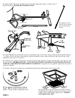
Handle Shaft
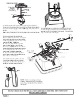
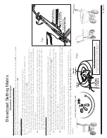
14.
Install (1) 1/4-20
Hex nut (not a locknut)
on to control rod as
shown.
15.
Install flattened end of control rod in to lever on gauge as shown. Turn to lock in place. Next push lever forward to setting
“0”. Align control rod with hole in pivot bracket, pull lever backward to insert control rod through hole in pivot bracket. Now
install 1/4-20 Hex nut on to control rod.
16.
Pull lever back to setting “30” as shown. Next push pivot & bracket forward so that the shut off plate in the hopper is in the
full open position.
REMEMBER SETTING “30” ON THE FLOW CONTROL LEVER MUST PLACE THE SHUT-OFF PLATE
IN THE FULL OPEN POSITION TO BE PROPERLY CALIBRATED.
Now tighten the nuts against the pivot bracket to prevent
change in calibration.
17.
Tension on the flow control lever may be adjusted by tightening or loosening the tension nut as shown.
¼
-20
Hex Nuts
Pivot
Bracket
Control
Rod
Pivot
Rod
18.
Insert agitator to pinion shaft on inside of
hopper.
Note:
the position of flat side of the
agitator. This pin should be installed as shown.
PAGE 4
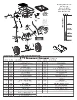
13.
Install handle shaft to lower handles and pivot & bracket assembly as shown. Using 1/4 -20 x 2”
bolts and locknuts.
TIGHTEN BOLTS AND NUTS NOW.
1/4-20 x 1”
Hex Head Bolt
Stainless
1/4-20 Lock Nut
Stainless
19.
Install debris screen into hopper, then insert 1/4-20 x 1”
Stainless Steel Hex Bolt thru the hole in the side wall of the
hopper. Secure with Stainless Steel lock nut -
TIGHTEN
WITH HAND TOOLS ONLY


