EarthQuake 7050 Скачать руководство пользователя страница 6

6

ARDISAM

SAFETY RULES

OPERATION

Never operate the tiller without guards, covers, and
hoods in place.

Never start the engine or operate the tiller with the
wheels in the free-wheel position. Make sure the
wheel lockouts or lockpins are engaged through
wheel hubs and wheel axle. The wheels act as a
brake to keep the tiller at a controlled speed.
Disengage wheels to permit free-wheeling only when
engine is stopped.

Keep hands, feet, and clothing away from rotating
parts. Keep clear of tiller tines at all times.

Tines and wheels rotate when tiller is engaged in

forward

 or 

reverse

-- in 

forward

, tines and wheels

rotate when the drive safety control levers are pulled
down; in 

reverse

, wheels and tines rotate when the

reverse handle is pulled back towards the operator.
Releasing the drive safety control levers to 

neutral

stops the wheels and tines.

Be extremely cautious when operating in 

reverse

.

Take extra care to avoid slipping or falling, and to
keep feet clear of tines.

Exercise extreme caution when operating on or
crossing gravel drives, walks, or roads. Stay alert for
hidden hazards or traffic.

After striking a foreign object, stop the engine,
remove the wire from the spark plug, thoroughly
inspect the tiller for any damage, and repair the
damage before restarting and operating the tiller.

If vegetation clogs the tines, raise the handlebars to
elevate the tines, and run the tiller in 

reverse

. If this

does not clean clogged vegetation from the tines,

STOP THE ENGINE AND DISCONNECT THE
SPARK PLUG WIRE 

before removing vegetation

by hand.

Engine muffler will be hot from operation. Do not
touch it with bare skin or a severe burn may result.

If the unit should start to vibrate abnormally, stop
the engine and check immediately for the cause.
Vibration is generally a warning of trouble.

Do not run the engine indoors; exhaust fumes are
dangerous.

Do not overload the machine capacity by attempting
to till too deep at too fast a rate.

Never operate the machine at high transport speeds
on slippery surfaces. Look behind and use care
when backing.

Never allow bystanders near the unit.

Use only attachments and accessories approved by
the manufacturer of the tiller.

Never operate the tiller without good visibility or
light.

Be careful when tilling in hard ground. The tines may
catch in the ground and propel the tiller forward. If
this occurs, let go of the handlebars and do not
restrain the machine.

Take all possible precautions when leaving the
machine unattended. Disengage all controls levers,
stop the engine, wait for all moving parts to stop,
and make certain guards and shields are in place.

When leaving the operating position for any reason:
- shut off the engine.
- wait for all moving parts to stop.

MAINTENANCE AND STORAGE

Keep machine, attachments, and accessories in
safe working condition.

Check shear bolts, engine mounting bolts, and other
bolts at frequent intervals for proper tightness to be
sure the equipment is in safe working condition.

To prevent accidental starting, always disconnect
and secure the spark plug wire from the spark plug
before performing tiller maintenance.

Never run the engine indoors. Exhaust fumes are
deadly.

Always allow muffler to cool before filling fuel tank.

Never store equipment with gasoline in the tank
inside a closed building where fumes may reach an
open flame or spark. Allow the engine to cool before
storing in any building.

Always refer to the operator's guide instructions for
important details if the tiller is to be stored for an
extended period.

Содержание 7050

Страница 1: ... Rev 020304 Copyright 2004 Ardisam Inc All Rights Reserved Printed in USA Bumper Guard is a standard feature on Model 7155 Gear Drive Rear Tine Rototiller Operator s Manual Includes Models 7155 7055 7050 R R ...

Страница 2: ...2 ARDISAM ...

Страница 3: ...ply with all safety and operating instructions in this manual before attempting to setup and operate your rototiller Failure to comply with all safety and operating instructions can result in loss of machine control serious personal injury to you and or bystanders and risk of equipment and property damage The triangle in the text signifies important cautions or warnings which must be followed Engi...

Страница 4: ...ll repairs made under warranty must have prior approval from Ardisam Inc Items subject to normal wear and tear such as belts batteries tines shear bolts and tires due to the nature of their function are not covered under this warranty Any unit used in a commercial application is covered for a period of 90 days after purchase The engine is covered under a separate warranty issued by the engine manu...

Страница 5: ...ately when operating the tiller Always wear sturdy footwear Never wear sandals sneakers or open shoes and never operate the tiller with bare feet Do not wear loose clothing that might get caught in moving parts Carefully inspect the area to be tilled and remove all foreign objects Do not till above underground water lines gas lines electric cables or pipes Do not operate the tiller in soil with la...

Страница 6: ...he unit should start to vibrate abnormally stop the engine and check immediately for the cause Vibration is generally a warning of trouble Do not run the engine indoors exhaust fumes are dangerous Do not overload the machine capacity by attempting to till too deep at too fast a rate Never operate the machine at high transport speeds on slippery surfaces Look behind and use care when backing Never ...

Страница 7: ...ion and content of the safety messages you will see as you perform normal tilling operations Please review these labels now and if you have any questions regarding their meaning or how to comply with these instructions reread the complete safety instruction text on the preceding pages or contact your local dealer Should any of these labels become unreadable because of being worn faded or otherwise...

Страница 8: ...060 drive safety control lever reverse handle reverse cable depth regulator lever forward cable detent pin belt guard wheel lockouts standard on Model 7060 serial number plate recoil start bumper guard standard on Model 7060 R R ...

Страница 9: ...d remove machine by a Removing lockouts on wheels b Roll tiller from carton The right and left sides of your rototiller are determined from the operating position as you face the direction of forward travel ATTACH HANDLEBAR TO TILLER 1 Place handlebar stems on outside of transmission cover and align lower holes 2 Insert one 3 8 16 x 1 bolt for each side in lower holes 3 Start 3 8 16 nuts on each b...

Страница 10: ...high quality detergent oil Container must be marked A P I Service SF SJ Use no special additives with recommended oils Do not mix oil with gasoline Oil level must be full Check the oil level by removing oil fill plug Oil level should be up to the bottom of the fill plug opening 2 Always check oil level before starting engine Refer to engine manual for capacity and type of oil to use depth regulato...

Страница 11: ... levers disengages the wheels and brings the tiller to a complete stop It is now in the neutral position Drive Safety Control Levers Engaged reverse handle This information is provided here only to introduce the controls DO NOT START THE ENGINEAT THIS TIME Starting and operating instructions are given on page 12 Please read this section and all operating and safety instructions before starting you...

Страница 12: ...Repeat for other wheel NOTE Always have both wheel lockouts in or out Do not operate tiller with only one wheel locked To place wheels in free wheel position 1 Remove lockpin Slide wheel inward toward machine 2 Insert pin in axle only 3 Wheel should turn freely on axle HANDLEBAR HEIGHT ADJUSTMENT Adjust handlebar height The ideal height of the handlebar varies with operator height and the depth of...

Страница 13: ...epth Regulator Lever Down Shallower tilling Place the detent pin in the top hole of the depth regulator lever for shallowest tilling Depth Regulator Lever Up Deeper tilling Place the detent pin in the bottom hole of the depth regulator lever for deepest tilling BELT TENSION ADJUSTMENT Proper belt tension is critical to good performance After 1 2 hour of operation all cables may have to be adjusted...

Страница 14: ...position before starting engine Tines should clear the ground ENGINE IS SHIPPED FROM FACTORY WITHOUT OIL YOU MUST ADD ENGINE OIL BEFORE STARTING ENGINE START UP The controls required to start and run the rototiller are located on the engine and are marked Choke and Throttle A more detailed description of engine operation and all related precautions and procedures can be found in the engine manufac...

Страница 15: ... adjusting the depth regulator lever Practice operating the controls and tiller with tines out of ground before beginning to till It is important that you know how to use the tiller properly how to keep control at all times how to stop the tines and wheels from turning and how to stop the engine if necessary If you do not know how to do these things read the Controls Adjustments and Safety section...

Страница 16: ...tall grasses vines or other materials clog or jam the tines reverse the tiller to unwind vegetation Immediately release the drive control levers if the tines jam or you strike a foreign object With drive control levers in neutral push throttle control to stop position to stop the engine Disengage the spark plug wire When tines have stopped remove foreign objects and check for damage CULTIVATING TI...

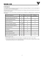
Страница 17: ... Change oil after first 5 8 hours of use then after every 50 hours or every season Change oil every 25 hours when operating under heavy load or in high temperatures n o i t a r e p O e c n a n e t n i a M e g a P e s U h c a E e r o f e B r o s r h 0 5 n o s a e S y r e v E n o i s n e t t l e b e s r e v e r d r a w r o f k c e h C 6 1 X t l e b e s r e v e r d r a w r o f e g n a h C 7 1 X e c n...

Страница 18: ...ittle belt tension will cause premature belt failure To check and adjust the forward belt tension 1 Turn off engine Engine must be cool 2 Remove and secure spark plug wire from spark plug 3 With drive safety control levers in neutral position measure length of spring when compressed 4 Pull down on drive safety control levers and remeasure length of spring when stretched out Ideal length would be 1...

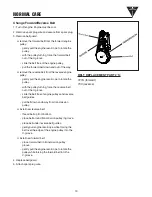
Страница 19: ... engine pulley gently pull the engine recoil rope to rotate the pulley with the pulley turning force the reverse belt out of the V groove slide the belt free of engine pulleys and reverse belt guides pull belt down and away from transmission pulley install new reverse belt thread belt up from bottom place belt around transmission pulley in groove place belt under reverse belt guides gently pull en...

Страница 20: ... included in your parts packet for information on engine maintenance Your engine manual provides detailed information and a maintenance schedule for performing the following tasks 1 Check oil level before each use or after every 8 hours of operation 2 Change oil after first 5 8 hours of operation Change oil while engine is warm Refill with new oil of recommended grade 4 Check spark plug yearly or ...

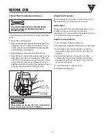
Страница 21: ... Tip the tiller back to a level position 6 Replace spark plug wire When replacing grease the tiller transmission holds 18 22 ounces DO NOT OVERFILL Check Tiller Transmission Grease Check the grease level annually To check the grease level 1 Move tiller to level ground 2 Remove grease level dipstick located between the handlebar mounts in the front transmission cover Correct grease level is indicat...

Страница 22: ...e of SAE 30 oil into spark plug hole 6 Plug hole and pull starter cord slowly to distribute oil evenly in cylinder head area 7 Reinstall spark plug 8 Transport unit to a suitable storage location If you have chosen to use a fuel stabilizer and have not drained the fuel system follow all safety instructions and storage precautions in this manual to prevent the possibility of fire from the ignition ...

Страница 23: ...urches forward Tines turn wheels do not turn Tines turn wheels turn tiller does not move Add gas to gas tank Connect spark plug wire to spark plug Throttle must be positioned at choke for a cold start Clean or replace air cleaner Drain old fuel and replace with fresh Use gas stabilizer at end of season Make sure spark plug wire is securely attached to spark plug Drive safety control levers must be...

Страница 24: ...arance between belt guide and belt replace belt guard and spark plug wire Adjust tabs on the reverse belt guide turn engine off and allow muffler to cool disconnect spark plug wire and secure from spark plug release drive safety control levers to neutral remove belt guard adjust tabs of reverse belt guide while drive safety control levers are released bend metal tabs on reverse belt guide to 1 64 ...

Страница 25: ...______________ ______________________________________________________________ ______________________________________________________________ ______________________________________________________________ ______________________________________________________________ ______________________________________________________________ ______________________________________________________________ _______...

Страница 26: ...26 ARDISAM 7155 7055 7050 Handlebar Assembly ...

Страница 27: ... Pivot 5 16 2102 4 Bolt Hex Hd 3 8 16 x 1 Grade 5 2104 4 Nut Hex 3 8 16 53530 1 Spring Bee Hive Forward Cable Adjust 53572B 1 Drive Control Lever 53575 1 Bracket Drive Control Lever Right 53575A 1 Bracket Drive Control Lever Left 53588 1 Reverse Handle 53604 4 Cap Screw Button Hd 10 24 x 3 8 53606 6 Nut Nyloc 10 53607 4 Nut Jam 5 16 24 53608 1 Reverse Link 53630 2 Cable Assembly 53631 2 Handle Gri...

Страница 28: ...28 ARDISAM 7155 7055 7050 Tines Hood Assembly Rev 031203 ...

Страница 29: ...415A 1 Hood Tiller w Side Shields w o Decals 417 2 Bolt Hex Hd 5 16 18 x 1 2 Grade 5 504 2 Lockwasher Spring 5 16 509 2 Bolt Hex Hd 1 4 20 x 1 2 719 2 Lockwasher Spring 3 8 1900LCRT 1 Tine Set Left Side Comlete Assembly 1900RCRT 1 Tine Set Right Side Comlete Assembly 2001 2 Bolt Hex Hd 3 8 16 x 1 3 4 2104 2 Locknut Hex 3 8 16 69170 1 Detent Pin 5 16 x 2 ...

Страница 30: ...30 ARDISAM 7155 7055 7050 Motor Mount Assembly ...

Страница 31: ... Left Side 1101AD 1 Wheel TireAssembly Left Side 1102A 1 Wheel TireAssembly Right Side 1102AD 1 Wheel TireAssembly Right Side 1103 2 Lockpin 1103A 2 Knob Wheel Lockout 1103B 2 Butterfly Set of 2 1103C 2 Snap Ring 1105 2 C Clamp Lockout Wheels 7155 1407 2 Spring IdlerArm 1408 2 Pulley Forward Reverse Idler 1410 1 IdlerArm Forward 1416 2 Link Pin Forward Reverse 1418 2 Cotter Pin 1439 2 Washer 1 4 I...

Страница 32: ...5 16 18 x 3 4 Grade 5 1504 2 Gasket Tiller Housing Transmission Cover 1506 4 Seal Tiller Housing 1507 2 Gasket Front Rear Bearing Cap 1508 1 Cap Rear Bearing 1511 3 Bolt Hex Flange Hd 1 4 20 x 7 8 1514 1 Cap Front Bearing 1515 1 Oil Seal Drive Shaft 1516 3 Bolt Hex Flange Hd 1 4 20 x 3 4 1517 1 Kit Oil Seal Gasket Includes two 1504 four 1506 two 1507 one 1515 1690 1 Transmission Lube 00 1 Qt 53413...

Страница 33: ...4 x 1 1702 1 Gear Worm Brass 61 Tooth Wheel Shaft 1703 4 Shim Set Axle Spacer Kit 1704 4 Bushing 1705 4 Shim 1 375 OD x 062 thick as req d 1706 2 Shim 1 375 OD x 030 thick as req d 1710 2 Snap Ring Retainer External 1801 1 Tiller Shaft Assembly 1803 1 Gear Worm Brass 30 Tooth 1804 4 Spacer 1 250 x 1 000 x 062 thick 1805 2 Shim Set Bearing Cap 1806 6 Shim 1 750 OD x 062 thick as req d 1807 2 Shim 1...

Страница 34: ... 1 1702 1 Gear Worm Brass 61 Tooth Wheel Shaft 1703 4 Shim Set Axle Spacer Kit 1704 4 Bushing 1705 4 Shim 1 375 OD x 062 thick as req d 1706 4 Shim 1 375 OD x 030 thick as req d 1710 2 Snap Ring Retainer External 1801 1 Tiller Shaft Assembly 1803 1 Gear Worm Brass 30 Tooth LH Tiller Shaft 1804 4 Spacer 1 250 x 1 000 x 062 thick 1805 2 Shim Set Bearing Cap 1806 6 Shim 1 750 OD x 062 thick as req d ...

Страница 35: ...ware pictured below Follow diagram below for placement of parts Adjust left and right wing carriage bolts in slots to get correct leveling of hills The furrower attaches to your tiller in just one easy step Remove the hex bolt and nut inserted through the bracket and align with hole in drag stake holder just behind the drag stake under the hood Insert hex bolt and nut and tighten securely bracket ...

Страница 36: ...Ardisam Inc 1690 Elm Street Cumberland Wisconsin 54829 715 822 2415 Fax 715 822 4180 1 800 345 6007 www ardisam com ...

Отзывы: