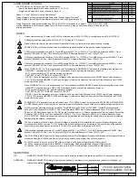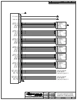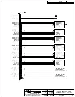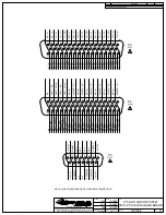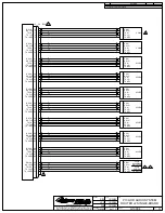
NOTES:
Unless otherwise noted: All wires are 22 AWG; all shielded wire is MIL-DTL-27500; all unshielded wire is MIL-W-22759/16.
All Bonding and Grounding will be I/A/W AC 43.13-1B, Chapter 11, Section 15.
Ground the shield return to the metal connector backshell if used, or otherwise to the metal connector housing.
SPARE KEY line function and connections are installer defined and depend on the specific system configuration.
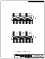
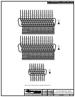
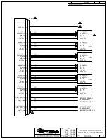
D50M connector assembly consists of: Tyco/AMP housing 205170-1 or 1757819-5; Tyco/AMP pin contacts 205089-1; Cinch
backshell DD-24661-34; 2ea. Cinch Screwlocks D20420-0. Alternate Backshell: Conec 165X10179X.
D50F connector assembly consists of: Tyco/AMP housing 205169-1 or 1757820-5; Tyco/AMP socket contacts 205090-1; Cinch
backshell DD-24661-34; 2ea. Cinch Screwlocks D20420-0. Alternate Backshell: Conec 165X10179X.
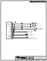
D9F connector assembly consists of: Tyco/AMP housing 205161-1 or 1757820-1; Tyco/AMP socket contacts 205090-1; Cinch
backshell DE-24657-30; 2ea. Cinch Screwlocks D20419-46. Alternate Backshell: Conec 165X10139X.
2.
1.
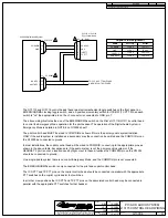
When COM1DIR (P5, Pin 10) is not grounded, the Pilot headset is in EMERGENCY mode and the following lines are diverted:
- HEADSET 1 connects directly to RX1, RX11 (Unswitched Alert Tones) and the emergency intercom.
- MIC 1 connects directly to TX1 and the emergency Intercom.
- XMIT KEY 1 and PLT COM1 KEY connect to TX KEY 1.
- ICS KEY 1 keys the emergency intercom, if at least one Power Input Circuit Breaker to the G13000 Audio Router has power.
- TX11 (CVR) transmits HEADSET1, MIC1 and Emergency Intercom if at least one Power Input Circuit Breaker to the G13000
Audio Router has power.
MAKE NO CONNECTION. The pin is not connected to anything internally and therefore shall have no connection externally
DEFINITIONS:
N/C:
RESERVED:
MAKE NO CONNECTION. Internal circuitry may be added in the future, or may be present and relevant for testing but not
relevant to operation for flight.
4
5
6
7
8
9
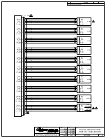
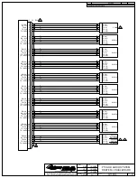
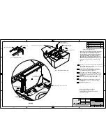
TERMINAL BLOCK assembly consists of: Deutsch block CTJ122E05E; Deutsch socket contacts CTS-S22/22 or M39029/22-191.
A GNET channel that is connected to only one control panel or other device may be wired directly without using a terminal block.
10
D15FS connector preferred assembly consists of: Tyco/AMP housing 205163-1 or 1757820-2; Tyco/AMP socket contacts
205090-1; Cinch backshell DA-24658-31; 2ea. Cinch Screwlocks D20419-46. Alternate Backshell: Conec P/N: 165X10149X.
Splices on 20 AWG wire shall also be 20 AWG, length 3 inches maximum. Alternate assembly consists of: Kobiconn Solder-Cup
Connector 156-1315(T-E) and Cinch backshell DA-24658-31; 2ea. Cinch Screwlocks D20419-46. Alternate Backshell: Conec
P/N: 165X10179X. Conductors shown with splices may be implemented by soldering the supply wire to both pins after soldering
and insulating the adjacent connections.
THIS DOCUMENT INCLUDES INFORMATION PROPRIETARY TO GENEVA
AVIATION AND SHALL NOT BE USED OR DUPLICATED BY ANYONE
WITHOUT THE WRITTEN PERMISSION OF GENEVA AVIATION, INC.
www.genevaaviation.com
SHT.
DATE
DATE
DATE
APPROVAL
PRO NO.
DRAWN
CHECKED
DWG NO.
TITLE
REV.
REVISION
DESCRIPTION
REV
APPROVAL
DATE
G13004
H
P139-HD AUDIO SYSTEM
WIRING DIAGRAMS - NOTES
GA182
1 of 13
RBH
10/30/08
JSW
10/30/08
CLB
10/30/08
11
The Audio System works with a range of supply voltages, as specified in the installation instructions. Breaker ratings and wire
sizes shown are for 28V systems. For 12V systems, the breaker ratings must be increased to 10A and the size of the shielded
supply and ground wires must be increased to 18 AWG. The splice wires at P5 remain at 20 AWG.
A
Changed Connector Part Numbers
5/28/09
GA
B
Added Single Audio Board Option
6/10/11
GA
The P139-HD can be set up in one of two configurations:
-- Dual Audio Board system with 4 audio connectors J1, J2, J3, J4
-- Single Audio Board with 2 audio connectors J2 and J4
Pages 1, 11 and 12 are common to all installations.
Wiring diagrams for the Dual Audio Board system are found on pages 2 through 7
Wiring diagrams for the Single Audio Board system are found on pages 8 through 10
Wiring Diagram for using pysical switches on G13115/G13116 Control heads is on page 13. G13115NS or G13116NS
may be substituted in any location besides Pilot or Co-Pilots locaction or may be used in any location if they are not the
primary audio panel.
AUDIO BOARD OPTIONS:
D9M connector assembly consists of: Tyco/AMP housing 205162-1 or 1757819-1; Tyco/AMP socket contacts 205089-1; Cinch
backshell DE-24657-30; 2ea. Cinch Screwlocks D20419-46. Alternate Backshell: Conec 165X10139X.
12
C
Added Wiring for G13115/G13116 Control Panel
3/02/12
GA
When COM2DIR (P5, Pin 11) is not grounded, the Copilot headset is in EMERGENCY mode and the following lines are diverted:
- HEADSET 2 connects directly to RX2, RX20 (Unswitched Alert Tones) and the emergency intercom.
- MIC 2 connects directly to TX2, and the emergency Intercom.
- XMIT KEY 2 and CPLT COM2 KEY connect to TX KEY 2.
- ICS KEY 2 keys the emergency intercom, if at least one Power Input Circuit Breaker to the G13000 Audio Router has power.
- TX20 (CVR) transmits HEADSET2, MIC2 and Emergency Intercom if at least one Power Input Circuit Breaker to the G13000
Audio Router has power.
The COM1DIR pin MUST be wired to an appropriate switch to control Emergency Mode for the pilot headset. Emergency Mode is
mandatory when the G13000 Audio Router is used as the primary audio system. See notes on sheet 13.
13
For EC135 connect alert tone ports to TB9 of factory wiring. See Eurocopter Maint.Manual WDM for detail.
For EC145 connect alert tone ports to TB55028 of factory wiring. See Eurocopter Maint. Manual WDM for detail.
For Bell 204, 205, 214 and 412 connect alert tone ports to 8Z1P3. See Bell Maint. Manual BHT-xx-MM for detail.
14
D
Added Alert Tone Information for EC135, EC145
4/16/12
SJC
E
Fixed Drawing Errors. Added G13115NS and G13116NS
10/29/12
SJC
3
F
Updated for Installation in Bell Medium Helicopters
12/3/12
SJC
G
Rewrote EMERG/NORMAL notes for clarity.
Removed support for older control panels.
3/26/14
SJC
H
Changed headset numbering scheme
Added external power for additional control panels.
4/24/14
SJC
Содержание P139-HD
Страница 2: ......
Страница 4: ......
Страница 5: ......
Страница 6: ......
Страница 7: ......
Страница 8: ......
Страница 16: ......
Страница 17: ......
Страница 19: ......
Страница 22: ......
Страница 23: ......
Страница 24: ......
Страница 26: ......
Страница 27: ......
Страница 28: ......
Страница 29: ......
Страница 30: ......
Страница 31: ......
Страница 32: ......
Страница 33: ......
Страница 34: ......
Страница 58: ......
Страница 60: ......
Страница 62: ......
Страница 64: ......
Страница 78: ......
Страница 80: ......
Страница 82: ......

