Geneva Aviation, Inc.
www.GenevaAviation.com
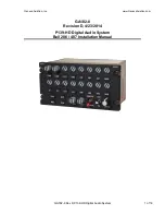
GA182-8 Rev D P139-HD Digital Audio System
3 of 16
The P139-HD Digital Audio Router contains no user serviceable internal
components. Do not disassemble router or the factory warranty will be
voided. For service, return the unit to Geneva Aviation.
1.3. There are three types of P139-HD Audio Systems that the installer may
choose to install at their discretion.
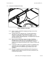
1.3.1. P139-HD (D) Uses Router G13000 in a
“Dual-board” configuration
and is shown in the diagrams and is the router used throughout the
instructions.
1.3.2. P139-HD (S) Uses Router G13000 in a
“Single-board” configuration
that uses the same case as the dual-board router, but with only one
audio board installed. These two routers share the same installation
and wiring drawings.
1.3.3. P139-HD (T) uses Router G13160 and is a
“Three board” router.
This installation replaces wiring drawing G13004 with drawing
G13162. Installation of this router is performed the in the same
manner as the other two routers with slight changes in the mounting
hardware as noted in the instructions.
1.4. Prior to installation of this system, it is the responsibility of the installer to
confirm by analysis or measurement, that the additional power requirement
will not exceed the capacity of the avionics bus or the aircraft’s electrical
system. Power consumption for this audio system is 5 amps at 28 volts.
The system is designed to use redundant power sources, both coming from
the master avionics bus. For each supply line, use a separate 5 amp fuse
or circuit breaker on a 28 volt aircraft and separate ground lines to two
separate ground points. Refer to G13004 for wire harness details. The
system will support supply voltages of 14
– 32 VDC.
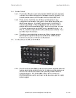
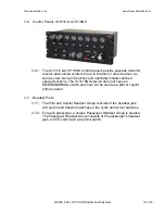
1.5. The internal power supply of the router is sufficient to power six audio
control panels. If the installation calls for more than six panels, the
additional panels must be powered from a separate circuit breaker to the
Router. Refer to G13004 sheet 12 for more information.
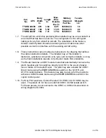
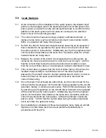
1.6. The FAA requirement regarding the securing of wire bundles using
nonmetallic clamps is addressed by the use of nylon cable ties. The part
numbers and description of these ties is as follows:
Following the guidelines in AC43.13-1B, cable ties are attached at a
maximum of 4” spacing and ties are attached to nylon cable tie anchors, as
necessary.
Содержание P139-HD
Страница 2: ......
Страница 4: ......
Страница 5: ......
Страница 6: ......
Страница 7: ......
Страница 8: ......
Страница 16: ......
Страница 17: ......
Страница 19: ......
Страница 22: ......
Страница 23: ......
Страница 24: ......
Страница 26: ......
Страница 27: ......
Страница 28: ......
Страница 29: ......
Страница 30: ......
Страница 31: ......
Страница 32: ......
Страница 33: ......
Страница 34: ......
Страница 58: ......
Страница 60: ......
Страница 62: ......
Страница 64: ......
Страница 78: ......
Страница 80: ......
Страница 82: ......


