Eagle A3 Pro Скачать руководство пользователя страница 4

[email protected]                                                                                                                                      4 


1.  Pay attention to the polarity of the plugs. The orange signal line must always be on the top and the brown on 

the bottom. 

2.  Check all the connectors and make sure that all of them are firmly connected to the sockets. 

3.  Please refer to the instructions of your transmitter for setting up the 3-position switch for flight mode control, 

and the knob (or slider) for remote master gain control.
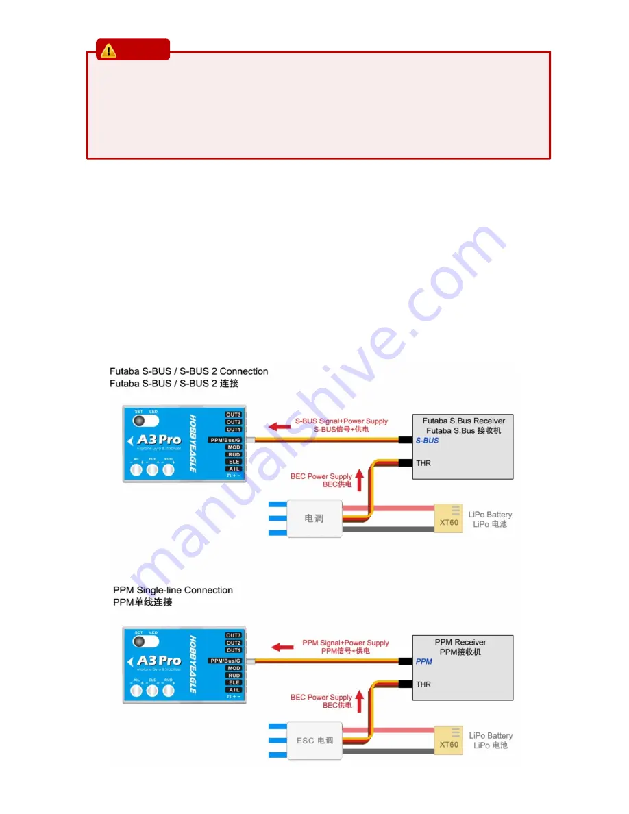


2.2.

PPM, S.BUS SINGLE-LINE RECEIVER CONNECTION


Using a single-line receiver (e.g. PPM receiver or Futaba’s S.Bus receiver) all channels are transferred by one single wire 

which connected to [PPM/Bus/G]. When a single-line receiver type has been selected, A3 Pro will load the default channel 

assignment to recognize the channels from receiver. The default assignment is: CH1=Aileron, CH2=Elevator, CH3=Throttle, 

CH4=Rudder, CH5=Flight Mode, CH6=Master Gain. You may program a different channel assignment manually in case the 

default assignment does not work with your transmitter’s function layout. A3 Pro supports a maximum of 8 channels when 

using a single-line receiver. When programing the channel mapping, select “None” for those channels you don’t want to 

use. 


CAUTION 

Содержание A3 Pro

Страница 1: ...wait for the gyro to initialize the initialization will take about 2 seconds and the LED will blink blue several times Don t move the plane and keep all the sticks in their original position until the initialization is done After a successful initialization the aileron servo will give you a short up and down move If the LED retains solid blue stop moving the plane then the initialization will star...

Страница 2: ...tion otherwise the gyro will not work normally when operating it in Trainer mode Auto Level and Auto Hover modes Flat face up socket pointing to rear Flat Inverted face down socket pointing to rear Upright button up socket pointing to rear Upright Inverted button down socket pointing to rear 1 You need only one piece of the tapes each time a soft or thick mounting may probably impact the performan...

Страница 3: ...on 1 in the Setup Menu PPM Bus G is used for remote master gain it allows you to adjust the master gain of the gyro by using a proportional knob or slider of the transmitter However connecting this channel is not a must if you don t want to change the gain in the flight PPM Bus G is also used as the input channel when a futaba s s bus or PPM single line receiver connection is being used Table 1 Po...

Страница 4: ...iver e g PPM receiver or Futaba s S Bus receiver all channels are transferred by one single wire which connected to PPM Bus G When a single line receiver type has been selected A3 Pro will load the default channel assignment to recognize the channels from receiver The default assignment is CH1 Aileron CH2 Elevator CH3 Throttle CH4 Rudder CH5 Flight Mode CH6 Master Gain You may program a different ...

Страница 5: ...top and lock its current position immediately This operation mode is well suited for practicing basic 3D maneuvers such as hovering or knife edge so we also call it 3D flight mode Since it can help you to lock the attitude of the plane it s also helpful for landing It is worth noting that when the gyro is operated in this mode the servos will keep driving to one side if a specific control input is...

Страница 6: ...he gyro to normal mode In case the plane starts to oscillate in flight then reduce the gain of the corresponding axis If the control feels weak and imprecise and doesn t hold position when stopping then increase the gain according to this approach fine tune the basic gain until you get the best performance 5 REMOTE MASTER GAIN The PPM Bus G is used to control the master gain remotely You can make ...

Страница 7: ...process is completed the gyro will get back into the operating mode if you want to perform another function of the menu you have to enter the Function Menu again Exiting the Menu To get out of the current menu just keep the button pressed 2 seconds again until LED starts flashing Green quickly Table 2 FUNCTION MENU Functions LED Status 1 Servo Trimming See 7 1 2 Travel Limiting See 7 2 3 Level Cal...

Страница 8: ...enient and more intuitive After entering this procedure move the elevator stick up or down to select one of the servos connected at OUT1 to OUT3 The current servo will indicate its selection to you by a short up and down move By default the servo connected at OUT1 is always the first one selected after you entering the procedure When the desired servo has been chosen move and hold the aileron stic...

Страница 9: ...OVER CALIBRATION As a same reason a hover calibration is recommended to perform after installation if you want to fly with Auto Hover mode The procedure is quite similar to that of level calibration The only difference is in the first step Before calibrating you need to lift the plane and make it vertical to the ground instead of putting it on the ground Short press the button when LED is flashing...

Страница 10: ...t Flat Inverted Upright Upright Inverted 3 Flight Mode White 3 flashes 1 Position 1 Blue 1 flash Gyro Off Normal Atti Lock Trainer Auto Level Auto Hover 2 Position 2 Blue 2 flashes Gyro Off Normal Atti Lock Trainer Auto Level Auto Hover 3 Position 3 Blue 3 flashes Gyro Off Normal Atti Lock Trainer Auto Level Auto Hover 4 Gyro Direction White 4 flashes 1 Aileron Blue 1 flash Normal Reversed 2 Eleva...

Страница 11: ...ng direction After entering in this function the color of LED shows you the orientation currently selected The default setting is Flat Red each short press of the button will switch to the next type After you finish making your selection just wait for 5 seconds until LED starts blink quickly which indicates that the modified is saved and then you will be brought back to the Setup Menu level automa...

Страница 12: ...s the button when LED is flashing 4 times in the Setup Menu to get into the Channel Selection Menu In this second level menu LED will flash Blue several times every 3 seconds in a loop and the number of times LED flashes shows at which channel you are currently For example one Blue flashing means Aileron after waiting about 3 seconds a twice Blue flashing means Elevator and so on When you reach th...

Страница 13: ...ckly move the right wing downward around the roll axis the right aileron surface should flap down and the left flap up as shown below Quickly move the nose of the plane downward around the pitch axis the elevator surface should flap up as shown below Quickly move the nose of the plane to the left around the yaw axis the rudder surface should flap right as shown below ...

Страница 14: ...LED shows you the frequency currently selected The default setting is 50Hz Red each short press of the button will switch to the next value After you finish making your selection just wait for 5 seconds until LED starts blink quickly which indicates that the modified is saved and then you will be brought back to the Setup Menu level automatically If you don t want to change anything just wait for ...

Страница 15: ...hat you wish to operate in short press the button to get into it After entering in the current selected option is indicated by the color of the LED Each short press of the button advances the option to the next value After you finish making your selection just wait for 5 seconds until LED starts blink quickly which indicates that the modified is saved and then you will be brought back to the Recei...

Страница 16: ...probably cause the mechanical characteristics changes of the sensor or replacement of new sensor etc The calibration should be done on a horizontal desktop and the gyro needs to be removed from the plane Entering the Calibration Program To access the accelerometer calibration program press and hold the button while turn on the receiver power supply release it when LED starts flash Violet slowly FY...

Страница 17: ...hold the button for 2 seconds until LED flashes Violet once slowly to confirm the reset After reset is done the gyro will start the initialization normally If you don t want to reset just remove the battery when LED is blinking in different colors 12 LED DESCRIPTIONS Blue Flashing Power on initialization and self test Solid Red Gyro Off Mode Solid Blue Normal Mode Blue Flashing Atti Lock Mode Soli...

Страница 18: ... 4g PWM 920uS 2120uS with 1520uS center length 50 333Hz Input Voltage 4 8V 8 4V Operating Temperature 10 50 Size 43 27 14mm Weight 10g excluding wires VOLTAGE PROTECTOR It s recommended to use the supplied 3300uF 16V capacitor to get a more stable and secure working voltage for the gyro The capacitor can be plugged onto any one of the free input or output sockets of the gyro or the receiver ...

Отзывы: