


8.5.
MAX TILT ANGLE
This function is used to setup the maximum allowed tilt angle of the plane
when operating in Trainer mode.
After entering in this function, the color of LED shows you the angle
currently selected. The default setting is
±
60deg (Green), each short press
of the button will switch to the next value. After you finish making your
selection, just wait for 5 seconds until LED starts blink quickly which
indicates that the modified is saved and then you will be brought back to the Setup Menu level automatically.
If you don’t want to change anything, just wait for timeout without any operation.
8.6.
SERVO FREQUENCY
This function is used to set the working frequency of the servos. The analog
servos can only work with 50Hz. If you don’t know what the maximum
update rate that is tolerated by your servos never use more that 50Hz. The
higher the frequency the better it is for the flight performance of the gyro but
you must check the servo specifications before increasing the setting.
Otherwise the servos may get damaged!
After entering in this function, the color of LED shows you the frequency
currently selected. The default setting is 50Hz (Red), each short press of the
button will switch to the next value. After you finish making your selection,
just wait for 5 seconds until LED starts blink quickly which indicates that the
modified is saved and then you will be brought back to the Setup Menu level automatically.
If you don’t want to change anything, just wait for timeout without any operation.
8.7.
GAIN LEVEL
This function is used to change the level of the basic gain. After entering in
this function, the color of LED shows you the gain level currently selected.
The default setting is Medium (Green), each short press of the button will
switch between Small, Medium and Large. After you finish making your
selection, just wait for 5 seconds until LED starts blink quickly which
indicates that the modified is saved and then you will be brought back to the
Setup Menu level automatically.
If you don’t want to change anything, just wait for timeout without any operation.
LED Color
Description
Solid Red
±
30deg
Solid Green
±
60deg (default)
Solid Blue
±
90deg
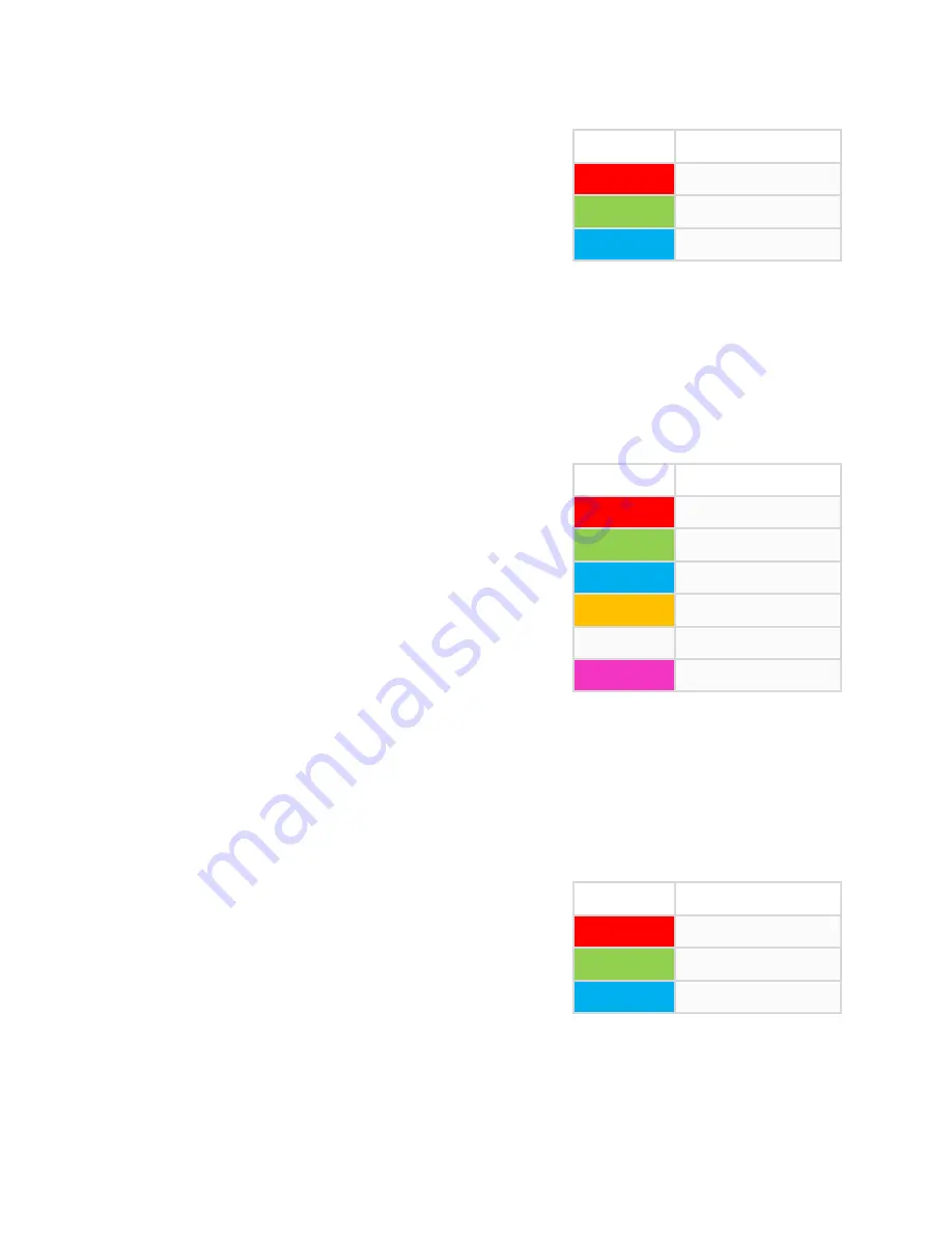
LED Color
Description
Solid Red
50Hz (default)
Solid Green
65Hz
Solid Blue
165Hz
Solid Yellow
200Hz
Solid White
270Hz
Solid Violet
333Hz
LED Color
Description
Solid Red
Small
Solid Green
Medium (default)
Solid Blue
Large