


Barksdale Height Control Valve Installation
Physical Description
The Barksdale Height Control Valve (HCV) is a three-mode valve used to control the
height of a vehicle by directing air to the air spring suspension. The main physical
features of the valve are the following; (2) delivery ports*, (1) Exhaust port, (1)
inlet/supply port, (1) Height Control Handle, and (2) ¼” Mounting Studs.
(* All ports are ¼” NPT, the (2) delivery ports are clearly marked, “C1” and “C2” on the
back of the valve.)
Modes of Operation
The three modes of operation of the HCV are as follows;
1. Fill Mode
2. Exhaust Mode
3. Dead Band Mode
When the vehicle suspension is at the factory set ride height, the valve will be in Dead
Band Mode. In Dead Band Mode, the Valve will not allow air to flow in or out of the air
bags. As the vehicle becomes laden, the suspension will settle, causing the handle of
the valve to rotate upwards. The valve will now enter Fill Mode, allowing air to enter the
air bags, causing the vehicle to rise. As the vehicle approaches factory set ride height,
the valve will once again enter Dead Band Mode. Similarly, if the bus is unloaded, the
suspension will rise causing the control handle of the valve to rotate downward. When
the handle rotates downward, the valve enters exhaust mode, thereby letting air out of
the air bags, causing the vehicle to lower until Dead Band Mode is reached again at the
factory set ride height.
Installation
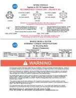
Attach all fittings to valve before mounting to vehicle. Thread sealant must be
applied to all fittings, which are tightened by hand until firm, at which point a wrench
should be used to tighten additional 1- 1 ½ turns.
Recommended proper orientation for the valve handle for installation is when the
valve handle is in line with the “C1” port.
Mount the Valve to a bracket using the ¼” studs. Do not fully tighten nuts at this
time, to allow fine-tune adjustment of ride height. Attach Air Supply line to the port at the
top of the valve. Attach the air bag air lines to the “C1” and “C2” ports.
Set-Up
1. Adjust approximate ride height by turning the valve handle up toward the air
supply line to add air to the bags to raise the vehicle above the ride height, down
to exhaust air from the air bags to adjust to approximate ride height. Then put
the handle in the horizontal position.
2. Install wood Centering Pin in hole provided in valve handle.
3. Connect linkage from suspension mount to valve handle and tighten linkage.
4. Adjust to final factory recommended ride height by rotating the valve assembly
on the bracket.
5. Tighten nuts to 45 Inch pounds torque.
6. Remove the centering pin.
Содержание 20 Ton XPT
Страница 3: ...Model 20 HAL Model 20 HALX Model 20 XPT Model 25 XPT Model 25 XPL Standard Model Drawings Page 1...
Страница 6: ...Page 4...
Страница 12: ...Page 10...
Страница 17: ...Page 15...
Страница 22: ...Page 20...
Страница 23: ...Page 21...
Страница 25: ...Page 23...
Страница 26: ...Page 24...
Страница 27: ...Page 25...
Страница 28: ...Page 26...
Страница 32: ...Page 30...
Страница 34: ...Page 32...
Страница 49: ......
Страница 55: ......
Страница 57: ......
Страница 58: ......
Страница 59: ...2017...