background image

2. Install cam roller assemblies onto the brake shoes. 

3. Install the camshaft into the spider. Install spacer wash-

er and lock ring on cam before sliding the cam thro u g h

the camshaft support bracket. Install the slack adjuster 

and the lock ring. 

10

N OTE  T

O E N S U R E B RA K E S M E E T

F. M . V.S.S. 121 

P E R

-

FO R M A N C E R E QU I R E M E N T S

, S

P I C E R

T

RA I L E R

P

RO D U C T S R E C O M

-

M E N D S T H AT O N LY O R I G I N A L E QU I P M E N T B RA K E C O M P O N E N T S B E

U S E D

.

WA R N I N G W

H E N R E A S S E M B L I N G B RA K E S

, S

P I C E R

T

RA I L E R

P

RO D U C T S R E C O M M E N D S T H AT T H E B RA K E R E T U R N

S P R I N G S B E R E P L AC E D W I T H N E W S P R I N G S TO A S S U R E P RO P E R

O P E RAT I O N O F T H E B RA K E

.

5. Remove brake re t u rn springs.

6. Remove camshaft lock ring, spacer washer, and cam

s h a f t .

7. Remove cam roller and shaft (in the case of the cast

shoe, remove roller shaft set screw and roller assembly)

and anchor pin bushing from shoes.

8. Remove anchor pin bushings, camshaft bushing and

seals from spider.

B RAKE ASSEMBLY

1. Install new anchor pin bushings, camshaft bushing 

and camshaft seals into the spider.

WARNING  W

H E N I N STA L L I N G C A M S H A F T S E A L S

T H E S E A L O N T H E S L AC K A D J U ST E R S I D E S H O U L D B E I N STA L L E D

W I T H S E A L FAC I N G I N TO S P I D E R

. T

H I S A L LOWS G R E A S E TO P U RG E

O U T S I D E T H E B RA K E A S S E M B LY W H E N G R E A S I N G T H E C A M S H A F T

BU S H I N G

. F

A I L U R E TO FO L LOW T H I SP RO C E D U R E C O U L D C AU S E

G R E A S E TO C O M E I N TO C O N TAC T W I T H B RA K E L I N I N G S

C AU S I N G

B RA K E FA I L U R E

.

4. Install the brake re t u rn springs on the brake shoes.

5. Position brake shoes on the spider and insert the 

anchor pins.

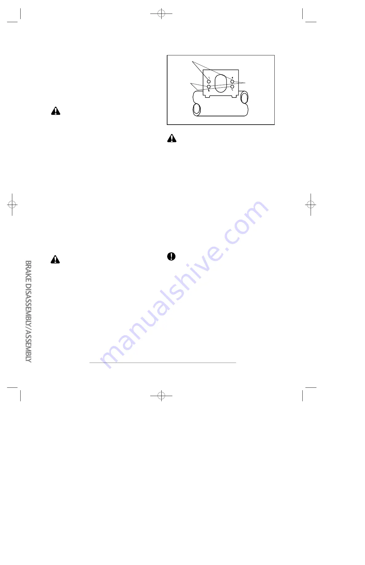
6. If air brake chambers are replaced, the correct mounting

holes must be used to correspond to brake adjuster length

(See Fig.4).

7. Connect slack adjuster to brake chamber push rod. 

8. Adjust brakes as outlined in brake adjustment 

p ro c e d u re s .

FIG. 4

6" B

RA K E

A

D J U ST E R

(A-A H

O L E S

)

5" B

RA K E

A

D J U ST E R

(B-B H

O L E S

)

5 1/2" 
B

RA K E

A

D J U ST E R

(A-B H

O L E S

)

Any questions or comments on the above pro c e d u re should

be directed to the Spicer Trailer Engineering Depart m e n t .

B RAKE DISA S S E M B LY / A S S E M B LY

C AUTION  E

XC E S S I V E P O U N D I N G O N A N C H O R P I N S

O R C A M RO L L E R P I N S TO R E M OV E O R I N STA L L T H E M C A N DA M AG E

T H E P I N SA N D C AU S E M I SA L I G N M E N T O F T H E B RA K E S P I D E RS A N D

B RA K E S H O E S

. T

H E U S E O F A S O F T H A M M E R O R B RA S S D R I F T

I S R E C O M M E N D E D TO R E M OV E O R I N STA L L T H E A N C H O R P I N S

I F N E C E S SA RY

.

B RAKE DISA S S E M B LY:

1. Release brakes and back off slack adjuster.

2. Remove slack adjuster lock ring and slack adjuster.

3. Remove brake dru m .

4. Remove anchor pins and brake shoes.

D22/P22 Manual pdf  9/23/97 2:48 PM  Page 12

Содержание 20 Ton XPT

Страница 1: ...es Co Inc 548 Swedesboro Ave Mickleton NJ 08056 Parts Service Manual New 2022 Edition Parts 800 338 7088 Sales 800 257 8163 EagerBeaverTrailers com ORDER GENUINE 20 Ton XPT 25 Ton XPT XPL 20 Ton XPT 2...

Страница 2: ...ented Roto Ring and Fixed D Rings 16 7 1 k c a J e r a u q S d e e p S 2 d n a l l o H F A S SAF Holland 2 Speed Landing Gear 18 9 1 s l e e h W s e r i T 0 2 y l b m e s s A h c t i H e y E 1 2 g n i...

Страница 3: ...Model 20 HAL Model 20 HALX Model 20 XPT Model 25 XPT Model 25 XPL Standard Model Drawings Page 1...

Страница 4: ...he trailer unloaded This will aid the trailer suspension in providing better weight distribution to all axles especially the rear Once the trailer is loaded the trailer should be level or just a bit h...

Страница 5: ...using a crossing pattern under the trailer tongue Make sure that there is sufficient slack in the chains to allow the trailer to fully articulate without the chains getting to tight and yet not having...

Страница 6: ...Page 4...

Страница 7: ...2059170 1 20 HAL WHITE 2059294 2 20 HALX WHITE 2060841 2 20 XPT WHITE 2062014 2 25 XPT WHITE 2062171 2 25 XPL WHITE 14 2059249 40 BLUE STRIPE EB YELLOW TRAILERS 2061081 40 WHITE STRIPE RED BLUE BLACK...

Страница 8: ...2060455 10 Cam Repair Kit One Per Axle 2062013 11 Slack Adjuster 2061083 not shown Auto Slack Adjustment Bracket 2061084 12 Air Brake Chamber 2059596 Note Items 8 11 are D22 Axle Unique and can NOT be...

Страница 9: ...Repair Kit In CAM Repair Kit In CAM Repair Kit In CAM Repair Kit In CAM Repair Kit In CAM Repair Kit t e e h s k r o W e e S r e t s u j d A k c a l S 1 2 22 Grease Fitting In CAM Repair Kit CAMSHAFT...

Страница 10: ...the distance from the head to the end of the cam Step 3 Measure the diameter of the cam at both C just behind the head and D just inside the spline Step 4 Finally determine whether the cam is a 10 sp...

Страница 11: ...86 31mm H steel wheels in out Flange Nut Short 342431 27mm H steel in alum wheel out 10 Oil Cap w plug 2055089 Cap includes window plug 11 Gasket oil cap 2055090 12 Oil cap window kit 2058056 Window g...

Страница 12: ...Page 10...

Страница 13: ...ys Only Begin 7 2009 10 Spline 2060755 Spicer Haldex 20 25 Ton older Curved 28 Spline 2061083 Spicer Haldex 20 25 Ton 7 7 0 8 5 0 2 e n i l p S 0 1 t h g i a r t S Manual Before Oct 1994 0 8 4 9 5 0 2...

Страница 14: ...82131 2062216 25XPT XPL 6 Long 15 Bucket Double Acting 425 00 850 00 992841 25GLB 5 Long 13 Bucket 325 00 650 00 992824 2054764 35Ton up GHG GLB All GSL BR 5 Long 13 Bucket 350 00 700 00 991828 ALL 35...

Страница 15: ...vot Pin 8 2059020 Roll Pin Ramps 9 2062169 Light Weight Ramp Fixed Link 3 8 thick for 15 20 Ton 9 2059195 Light Weight Ramp Fixed Link 1 2 thick for 25 Ton none 2062333 Tailboard standoff 1 2 x 3 4 x...

Страница 16: ...o March 2008 r e d r O l a i c e p S S S E N R A H X O B L O R T N O C 5 6 HARNESS WITH DEUTSCH DT06 6S CONNECTOR 392612 For waterproof switch only After Mar 2008 r u o h r e P p m A 5 5 y l l a c o L...

Страница 17: ...Page 15...

Страница 18: ...ter 3 2060620 Base Part Description 2054792 1 Diameter 15 000 Working Load Limit 2054733 Diameter 6 130 Working Load Limit Roto Ring 15 000 Lbs 360 Degree Working Load Limit Complete Roto Ring Assembl...

Страница 19: ...PIN x 1 5 2062321 6 TOP COVER 2062307 7 GEAR BOX HALF Outside 2062319 8 OUTPUT GEAR 2062311 9 JACK SHAFT 2062313 10 INPUT GEAR 2062312 11 SHIFT SHAFT 2062314 12 IDLER GEAR 2062310 13 BOSS BEARING 2061...

Страница 20: ...LONG 20 730112 7 211005 1 1 SCH 40 X 41 5 L G CROSS TUBE 8 412105 16 5 8 11X2 ZN HXHD CPSCRW GRD 8 9 412203 16 5 8 11 LOCKNUT UNC ZN 10 412304 32 5 8 US STD FLAT WASHER ZN 11 412101 2 3 8 16X2 5 ZN H...

Страница 21: ...s standard since 2002 Description Part Wheel 10 Stud BSM 6 75 X 17 5 2060234 Wheel Open Center 6 75 X 17 5 2059206 10 Stud BSM Ball Seat Mount used between 1999 2001 Demountable Rims Open Center used...

Страница 22: ...Page 20...

Страница 23: ...Page 21...

Страница 24: ...BRNCH TEE 13 381031 1 3 8T 3 8M STRAIGHT CONNECTOR 14 381153 1 3 4 HD NIPPLE SEALCO 6006 15 381156 2 3 4 MALE CON 3 4TUBEX3 4 16 2062024 1 AIR TANK 2850 HT 1242 2 PORT 17 2058065 1 REMOTE DRAIN VLV 3...

Страница 25: ...Page 23...

Страница 26: ...Page 24...

Страница 27: ...Page 25...

Страница 28: ...Page 26...

Страница 29: ...ER ALL PLUS 17 2062194 1 FRONT MARKER 2 LT 39 PLUS LED 18 2062195 1 FRONT MARKER 2 LT 81 PLUS LED 19 2062196 1 CNTR MARKER 4 POLE 51 PLUS LED 20 2062197 1 CNTR MARKER 4 POLE 87 PLUS LED 21 2062198 1 C...

Страница 30: ...eLoc Nut 875 9UNC incl w Bolt 3f Reducer fm 1 25 OD to 0 9 ID 2062029 4a Trac Align eccentric outer 2062031 4b Trac Align washer inner 2062032 5a Shock Absorber 2062170 5b Bolt 0 75 10UNC x 3 25 GR 5...

Страница 31: ...Bolt 3f Reducer fm 1 25 OD to 0 9 ID 2062029 4a Trac Align eccentric outer 2062031 4b Trac Align washer inner 2062032 5a Shock Absorber 2062170 5b Bolt 0 75 10UNC x 3 25 GR 5 2062035 5c Bolt 0 75 10UN...

Страница 32: ...Page 30...

Страница 33: ...IGHT CONN QCAB 11 381041 2 3 8 TUBE UNION TEE QCAS 12 381053 1 3 8T 1 4M SWVL BRNCH TEE QCAB 13 381878 20 3 8 0D NYLON BRAKE TUBING RED 14 381879 10 3 8 0D NYLON BRAKE TUBING BLUE 15 381880 10 3 8 0D...

Страница 34: ...Page 32...

Страница 35: ...uch changes 994684 25XPL with CUSH Lift No Pilot Air System Effective Jan 2007 Item Part No Qty Description Item Part No Qty Description 1 322096 1 CUSH CLC 25 005 LOW MT LIFT 12 2 991935 1 25K77T HP...

Страница 36: ...31 Safety Chain 1 2 x 41 with Clevis Hook 2059432 Weld on Anchor Safety Chain 5 8 x 8 2061064 Clevis Hook 1 2 Spring Loaded 2062129 Oblong Reflector Amber 2062130 Oblong Reflector Red 2060735 Eager Be...

Страница 37: ...ding Gear 2063008 Note All Eager Beaver Trailers are manufactured with a steel tray plate in the draw bar Therefore Toolbox Lid Kits do NOT include a tray plate i e a toolbox bottom Should a tray plat...

Страница 38: ...nce Service General Engines Co Inc 548 Swedesboro Ave Mickleton NJ 08056 New 2022 Edition Parts 800 338 7088 Sales 800 257 8163 EagerBeaverTrailers com ORDER GENUINE 20 Ton XPT 25 Ton XPT XPL 20 Ton X...

Страница 39: ...stries Advancing the Practical Application of Suspension Technology Springfield MO 800 654 8824 417 862 5012 Fax 417 862 2317 www hutchensindustries com 4 Spring Suspension Series 7700 9700 HUTC_554_7...

Страница 40: ...values for each suspension fastener The oiled torque values in the first column are for new fasteners with lubricated threads When you are installing new components we recommend you lubricate the thr...

Страница 41: ...y replace the radius rod bushing and bolt Failure to replace these components will result in damage to the hanger spring seat and or radius rod 2b Next check the 1 2 20 radius rod clamp bolt which sho...

Страница 42: ...e way this can be done is by raising the trailer until the trailer weight is taken off the springs If the rocker is displaced or if the joint is loose then the rocker should be removed and the rocker...

Страница 43: ...should be replaced annually or at 100 000 mile intervals For severe or off highway service grease should be replaced semi annually or at 30 000 mile intervals Bearings should be packed by machine or...

Страница 44: ...bs Resulting end play should be 001 to 005 Note If end play is not 001 to 005 disassemble and repeat this procedure SPECIFICATIONS AXLE LOCATION SPICER BEARING SPICER BEARING INDUSTRY STD INDUSTRY STD...

Страница 45: ...OUR HEALTHAND MAY CAUSE SERIOUSRESPIRATORY OR OTHERBODILY HARM AVOIDCREATINGDUST DON T REMOVEBRAKEDRUM WITHOUTPROPER PROTECTIVE EQUIPMENT DO NOT WORKON LININGSWITHOUTPROPERPR OTECTIVEEQUIPMENT DO NOT...

Страница 46: ...SPIDER THIS ALLOWS GREASE TO PURGE OUTSIDE THE BRAKE ASSEMBLY WHEN GREASING THE CAMSHAFT BUSHING FAILURE TO FOLLOW THISPROCEDURE COULD CAUSE GREASE TO COME INTO CONTACT WITH BRAKE LININGS CAUSING BRA...

Страница 47: ...b and bearing assembly and brake assembly from the axle spindle Clean all oil or grease from the axle spindle 4 Install the sensor block on the fixture tool and attach the fixture tool to the axle spi...

Страница 48: ...applicable Check brake air chambers and slack adjusters Inspect brake rollers roller shafts anchor pins and bushings and replace if necessary Lubricate brake adjusters Check shoes for bent shoe ribs c...

Страница 49: ......

Страница 50: ...ght by locating and reading the information on the identification tag it is on the suspension trailing arm 2 If necessary rotate the control arm for the height control valve up to raise or down to low...

Страница 51: ...ailerneartheliftcontrolvalvethatstatesthis Afterthetrailerhasbeenloadedyoumaylowertheliftaxlebymovingtheliftcontrolvalvelever Since thetrailerloaded themainairbagsshouldinflateimmediatelytosameheighta...

Страница 52: ...When the handle rotates downward the valve enters exhaust mode thereby letting air out of the air bags causing the vehicle to lower until Dead Band Mode is reached again at the factory set ride height...

Страница 53: ...for assistance Serial numbers are located on the bar coded label on the side of the ECU Valve Assembly Easy StopTM 2S 1M 2S 2M 4S 2M 4S 3M ECU ModulatorValveAssembly Easy StopTM 2S 1M Basic ECU Modul...

Страница 54: ...OutletValve Enhanced Easy Stop TM Only Power Supply Over or under voltage current low or internal failure Easy StopTM External Modulator BU Enhanced Easy Stop TM Internal Modulator Failure InletValve...

Страница 55: ......

Страница 56: ...tenance http www hendrickson intl com pdfs trailer_PDFs L496 pdf Brake Maintenance http www hendrickson intl com pdfs trailer_PDFs L974 pdf Meritor Wabco ABS Premium ECU http www meritorwabco com Meri...

Страница 57: ......

Страница 58: ......

Страница 59: ...2017...

Отзывы: