3. Any type of blower or compressed air should not be used
to avoid blowing dust into busbar joints, tap off boxes or
circuit breakers. If there is accumulation of dust and dirt,
clean it off by using a soft brush, vacuum cleaner, or clean lint
free rags.
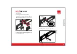
4. All joints should be correctly tightened according to the
torque value given and should be marked. Then install the
locking plates and transparent cover correctly.
5. All Tap Off boxes fed from the busbar should be in the
''OFF'' position.
6. The busbar runs should be isolated by disconnecting all
connections to transformers, switchboards, meters, etc.
7. Insulation resistance test with an insulation resistance test
equipment rated at 1000V AC should be conducted to verify the
integrity of the system.This test should be performed between
all phases, neutral and earth. Permanent records should be kept
of resistance readings. If the insulation reading appears to be
lower than 1 Mohm, then the cause should be investigated.
8. The system phase squence should be checked in order to
match the busbar phases sequence before reconnecting all
connections to transformers, switchboards, meters, etc.
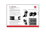
1- When installing the feeder boxes B10, B11 make sure that
the phase sequence of the feed box matches the phase
sequence of the busbar. (Make sure the neutral is correctly
connected)
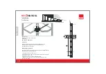
2- For multiway busbars check the position of the paralleling
conductor link, make sure that they are available and fitted
correctly. Do not remove these conductor links.
3- Cable glands should be selected according to the size and
number of feeder cables. Please consult our protection plant
for requirements other than the standard supplied.
4- Make sure that the incoming feeder cables to the box are
all the same length for each phase.
5- Do not cut or drill the feeder units.
Energizing
Before Energizing
1.
.
All busbar ratings, routings and supporting systems
should be checked as per the final isometric drawings.
2. All busbar systems should be checked visually to be
certain that they are clean and secure. Loose and/or
contaminated connections increase electrical resistance
which can cause overheating
KO-II
MANUAL
Installation
Cable Feed Box Installation
(B10, B11)
ENGLISH
17


