Installation, Operation and Parts Manual
EE-6215EKZ
13
4.2
Installation
attentions
4.2.1
Joints
of
oil
hose
and
wiring
must
be
firmly
connected
in
order
to
avoid
leakage
of
oil
hose
and
looseness
of
electrical
wires.
4.2.2
All
bolts
should
be
firmly
screwed
up.
4.2.3
Do
not
place
any
vehicle
on
the
lift
in
the
case
of
trial
running.
4.3
General
Installation
Steps
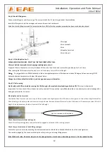
Step
1:
Remove
the
packaging,
take
out
the
carton
for
accessories
and
cover
plate.
Step
2:
Firstly,
put
something
supporting
between
the
two
posts
or
suspend
one
of
the
posts
by
a
crane
and
then
remove
the
bolts
on
the
package.
Attention
:
Please
pay
special
attention
not
to
let
the
post
fall
down
for
it
may
cause
casualty
or
bring
damages
to
the
accessories
fixed
in
the
post.
Step
3:
When
the
first
post
has
been
taken
away,
place
something
supporter
under
the
second
post
and
then
remove
the
bolts
on
the
package.
Step
4:
Fix
the
standing
position
for
the
two
posts.
(see
Annex
1,
floor
plan)
1.
Unfold
the
package
and
decide
on
which
post
the
power
unit
will
be
mounted.
2.
Draw
an
outline
of
the
base
plate
on
the
ground
with
chalk
and
ascertain
the
position
for
the
post.
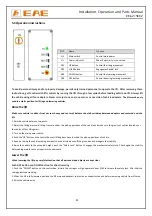
Step
5:
Connect
crossbeam.
Make
the
posts
face
to
each
other
and
the
distance
between
the
posts
equals
to
the
length
of
the
overhead
crossbeam.
Fix
the
beam
to
the
posts
by
screw
M12×20.
1.Hex
socket
cylinder
head
screw
M12*20
2.Spring
washing
M12
3.
Flat
washer
M12
4.
Overhead
crossbeam
5.
Vehicle
roof
protection
rod
6.
Post
1.Hex
bolt
2.Iron
rack
Содержание EE-6215EKZ
Страница 10: ...Installation Operation and Parts Manual EE 6215EKZ 10 3 4 Dimensions ...
Страница 27: ...Installation Operation and Parts Manual EE 6215EKZ 27 Annex 2 Electrical schemes and parts list ...
Страница 28: ...Installation Operation and Parts Manual EE 6215EKZ 28 ...
Страница 29: ...Installation Operation and Parts Manual EE 6215EKZ 29 ...


