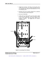
background image

1264C User Manual 

Chapter 4


UNDERSTANDING THE 1264C 

Overview 

The 1264C Mainframe consists of the following major functional 
blocks. 

• 

Power Supply 

• 

Backplane 

• 

Cooling System 

• 

System Monitor  

Figure 4-1

 shows the functional block diagram of the 1264C 

Mainframe. 


Power Supply 

The power supply accepts power from the AC mains and converts 
it to DC to power the following: 

• 

VXI modules installed into the backplane 

• 

Backplane terminations and daisy chaining logic 

• 

System Monitor board 


Power Supply 
Interconnections 

Power is supplied to the backplane through a board-to-board 
connection eliminating any wiring and sub-backplane interconnect 
boards. This design reduces the path impedance between the 
supply and the VXI modules receiving power, which results in 
improved dynamic current performance. See Appendix A for 
specifications. 

Remote sense correction is provided for the +5V, -2V, and –5.2V 
VXI supplies. The remote sense signals are routed from PS1 
through the monitor board (405141-J2) to the backplane via the 
14-pin ribbon cable (405141-J1 to 405130-J50). 

The Power Fail signal is routed from PS1 to the monitor board 
(405141-J2) and used to generate the VME signals ACFAIL* and 
SYSRESET*. These signals are then routed to the backplane 
through the 14-pin ribbon cable (405141-J1 to 405130-J50). 

EADS North America Defense 

                                  Understanding The 1264C 4-1 

Test and Services, Inc. © 1998 

Artisan Technology Group - Quality Instrumentation ... Guaranteed | (888) 88-SOURCE | www.artisantg.com

Содержание Racal Instruments 1264C

Страница 1: ...nderutilized and idle equipment along with credit for buybacks and trade ins Custom engineering so your equipment works exactly as you specify Critical and expedited services Leasing Rentals Demos In...

Страница 2: ...nadefense com helpdesk eads nadefense com http www eads nadefense com PUBLICATION DATE February 24 2003 Copyright 1998 by EADS North America Defense Test and Services Inc Printed in the United States...

Страница 3: ...e specific terms of your standard warranty or optional extended warranty or service agreement contact your EADS North America Defense Test and Services Inc customer service advisor Please have the fol...

Страница 4: ...s purchased and should ensure that they are used properly and in accordance with this handbook and any other instructions provided by Seller EADS North America Defense Test and Services Inc products a...

Страница 5: ...is will defeat the protective feature of the third conductor in the power cord Maintenance and calibration procedures sometimes call for operation of the unit with power applied and protective covers...

Страница 6: ...Artisan Technology Group Quality Instrumentation Guaranteed 888 88 SOURCE www artisantg com...

Страница 7: ...This page was left intentionally blank Artisan Technology Group Quality Instrumentation Guaranteed 888 88 SOURCE www artisantg com...

Страница 8: ...wer 1 5 Positive Pressure Cooling System 1 6 System Monitor 1 7 Rack Mount Options 1 7 Backplane 1 7 Items Shipped With The 1264C 1 8 Spares Optional Equipment 1 8 Chapter 2 2 1 CONFIGURING THE 1264C...

Страница 9: ...Monitoring Basics 3 3 Backplane Connections 3 4 Basic Functional Check 3 7 Chapter 4 4 1 UNDERSTANDING THE 1264C 4 1 Overview 4 1 Power Supply 4 1 Power Supply Interconnections 4 1 Power Supply Prote...

Страница 10: ...xterior Cleaning 5 2 Cleaning The Fan Filters 5 3 Modular Component Removal and Replacement 5 4 Tools Required 5 4 Removal and Replacement of The Fan Assembly 5 5 Removal and Replacement of The Power...

Страница 11: ...l iv Chapter 6 6 1 PRODUCT SUPPORT 6 1 Product Support 6 1 Warranty 6 1 Appendix A A 1 SPECIFICATIONS A 1 Specifications A 1 Artisan Technology Group Quality Instrumentation Guaranteed 888 88 SOURCE w...

Страница 12: ...cting Safety Ground 2 5 Figure 3 1 1264C Front View 3 1 Figure 3 2 1264C Rear View 3 2 Figure 4 1 Functional Block Diagram For 1264C Mainframe 4 2 Figure 4 2 System Monitor Block Diagram 4 5 Figure 5...

Страница 13: ...Ibus Slot 0 3 6 Table 3 5 Power Supply Voltages at the P1 and P2 Connectors 3 7 Table 5 1 Troubleshooting 5 12 Table A 1 AC Input Specifications A 1 Table A 2 DC Output Power A 2 Table A 3 Cooling A 3...

Страница 14: ...ns Fast Setup The 1264C backplane uses active automatic VME interrupt acknowledge and bus grant daisy chaining Manual configuration of backplane switch settings or jumpers has been eliminated Monitori...

Страница 15: ...nce 6 slot VXI mainframe 21 31L x 8 71W x 16 75H inches Figure 1 1 1264C Portable Mainframe In Bench Top Configuration Getting Started 1 2 EADS North America Defense Test and Services Inc 1998 Artisan...

Страница 16: ...me is designed for rack mounting in a 5U tall rack space Figure 1 2 1264C Rack Mount 5U Tall Configuration EADS North America Defense Getting Started 1 3 Test and Services Inc 1998 Artisan Technology...

Страница 17: ...etween the power supply and the VXI backplane The result is a low MTTR and high MTBF Figure 1 3 Modular Service Friendly Mainframe Design Features Getting Started 1 4 EADS North America Defense Test a...

Страница 18: ...oltage Figure 1 4 1264C 500 Watt Modular Power Supply Table 1 1 1264C Available DC Current VXI Voltage Available DC Current 5V 45 Amps 5 2V 30 Amps 2V 15 Amps 12V 8 Amps 12V 8 Amps 24V 4 Amps 24V 4 Am...

Страница 19: ...cooling to direct air to the VXI modules Figure 1 5 details the cooling system Figure 1 5 1264C Positive Pressure Cooling System Getting Started 1 6 EADS North America Defense Test and Services Inc 19...

Страница 20: ...ns 04 consist of rack mount ears only Backplane The 1264C backplane can accommodate up to six C size VXI modules The 1264C has a jumperless auto configurable backplane using active automatic daisy cha...

Страница 21: ...el Description Part Number Card Guide Cover Spare Card Guide Cover block air through unused slots 456271 Blanking Plate Blanking Plates to fill empty module slots 404836 Option 01 Rack Ears and Slides...

Страница 22: ...5VAC position Should it be necessary to replace the AC mains fuse F400 refer to Chapter 5 Removal and Replacement of the AC Mains Fuse NOTE Ordering Option 71 P N 407676 configures the 1264C for appli...

Страница 23: ...wer on Installation and Removal of Card Guide Covers In order to improve cooling of used slots in the VXI mainframe a limited number of the optional card guide covers P N 456271 may be installed at em...

Страница 24: ...f the cover and allow the snap in hook to rest on the cardguide 3 6 With a slotted screwdriver or similar flat bladed tool depress the spring hook 4 at a slight downward angle applying light pressure...

Страница 25: ...o unused or C size empty slots Secure with two captive mounting screws Refer to Figure 2 3 Mounting Screws Top and Bottom Blank Panel Figure 2 2 Blanking Panels Configuring The 1264C 2 4 EADS North Am...

Страница 26: ...grounding lug The wire insulation must be green with a yellow stripe or non insulated bare wire 2 Attach the opposite end of the wire to permanent earth ground earth or to the ground of one or more i...

Страница 27: ...ual This page was left intentionally blank Configuring The 1264C 2 6 EADS North America Defense Test and Services Inc 1998 Artisan Technology Group Quality Instrumentation Guaranteed 888 88 SOURCE www...

Страница 28: ...ront panel indicators Perform basic functional check of the mainframe VXI voltages Reference pin connections for VXI P1 and P2 Connectors 1264C Front Panel Monitor LED indicators S100 AC MAINS Switch...

Страница 29: ...off position 2 Connect the AC Power cord at J400 to the AC power source 115 VAC if S400 is set for 115VAC for the standard 1264C or 230 VAC if S400 is set for 230VAC if Option 71 is installed 3 Turn...

Страница 30: ...mation Refer to Section 7 Troubleshooting if a system fault is detected Table 3 1 Monitoring Basics WHAT YOU SEE ON THE FRONT PANEL WHAT IT MEANS Green LED illuminated for 5V 12V 24V 2V 5 2V 12V 24V V...

Страница 31: ...D14 8 D07 BG2IN D15 9 GND BG2OUT GND 10 SYSCLK BG3IN SYSFAIL 11 GND BG3OUT BERR 12 DS1 BR0 SYSRESET 13 DS0 BR1 LWORD 14 WRITE BR2 AM5 15 GND BR3 A23 16 DTACK AM0 A22 17 GND AM1 A21 18 AS AM2 A20 19 G...

Страница 32: ...V 14 LBUSA06 D16 LBUSC06 15 LBUSA07 D17 LBUSC07 16 GND D18 GND 17 LBUSA08 D19 LBUSC08 18 LBUSA09 D20 LBUSC09 19 5 2V D21 5 2V 20 LBUSA10 D22 LBUSC10 21 LBUSA11 D23 LBUSC11 22 GND GND GND 23 TTLTRG0 D2...

Страница 33: ...ODID06 D16 LBUSC06 15 MODID05 D17 LBUSC07 16 GND D18 GND 17 MODID04 D19 LBUSC08 18 MODID03 D20 LBUSC09 19 5 2V D21 5 2V 20 MODID02 D22 LBUSC10 21 MODID01 D23 LBUSC11 22 GND GND GND 23 TTLTRGO D24 TTLT...

Страница 34: ...25V P1 A31 12V 12 6 to 11 64V P2 C32 24V 25 2V to 23 28V P2 C13 2V 2 1V to 1 9V P1 C31 12V 11 64V to 12 6V P2 C31 24V 23 28V to 25 2V P2 C4 5 2V 5 46V to 5 044V P1 C9 P2 C3 Logic Ground If the voltage...

Страница 35: ...nual This page was left intentionally blank Operating The 1264C 3 8 EADS North America Defense Test and Services Inc 1998 Artisan Technology Group Quality Instrumentation Guaranteed 888 88 SOURCE www...

Страница 36: ...ect boards This design reduces the path impedance between the supply and the VXI modules receiving power which results in improved dynamic current performance See Appendix A for specifications Remote...

Страница 37: ...NEUTRAL AC NEUTRAL Fused AC LINE ACFAIL SYSRESET REMOTE SENSE TEMP SENSOR VOLTAGE MONITOR LED s TEMP LED FAN LED J300 P300 J301 P301 P50 J1 PS1 PF PS1 RS P2 J2 E1 TO E14 J50 PS1 TB1 P1 SLOT 0 5 P2 SLO...

Страница 38: ...voltage on the respective output may be reduced or at ground potential These protections are self correcting and the respective output will return to its nominal value when the fault is removed Backpl...

Страница 39: ...ure in the plenum forces the air through a metered plate into the P2 connector side of the VXI modules The air passing over components in the modules absorbs heat and exits at the P1 side of the modul...

Страница 40: ...ain Comparator Circuit TEMP LED Temperature Sensor Inverter LED Driver s Comparator Circuit J1 J2 ACFAIL SYSRESET Power on and Power Down Timing Circuit Power Fail ACFAIL SYSRESET Figure 4 2 System Mo...

Страница 41: ...or RT2 is isolated from the fan air stream The air flow detecting thermistor RT1 is in the air stream When the fan is operating properly the front panel LED is Green The LED will illuminate Red if the...

Страница 42: ...air is provided in this manual Service Interval Clean the fan filter optional at a maximum interval of six months Depending upon the amount of usage and ambient dust levels in the operating environmen...

Страница 43: ...ilters Refer to your module user documentation for information on cleaning the individual VXIbus modules CAUTION Always power off the mainframe and disconnect the power cord before cleaning or servici...

Страница 44: ...use chemical cleaning agents they may damage the mainframe Avoid chemicals that contain benzene toluene xylene acetone or similar solvents Cleaning The Fan Filters The fan filter optional is easily r...

Страница 45: ...Perform these procedures only as necessary as part of installation e g fuse replacement mainframe service or repair Refer to the Assembly Drawings in this chapter for an overview of the assembly and d...

Страница 46: ...power cord Loosen the retaining Phillips screws located on the rear and side panels of the mainframe Remove the rear panel with Fan towards the rear being careful not to damage the fan wiring 2 Disco...

Страница 47: ...y assembly from the mainframe Refer to Figure 5 3 and perform the steps below Power Supply Retaining Screws 4 Figure 5 3 Removing The Power Supply Maintenance 5 6 EADS North America Defense Test and S...

Страница 48: ...pulling apart 3 Disconnect J300 P300 4 Loosen the four screws which secure the power supply front panel to the mainframe Loosen the fourteen screws at E1 to E14 which secure the power supply to the ba...

Страница 49: ...will read correctly when the supply is in the proper orientation Align the U channel frame on guides 8 Gently guide the power supply forward until engagement with the backplane is felt 9 Tighten the...

Страница 50: ...el and rotate counter clockwise to remove 3 To replace fuse insert the fuse carrier and fuse assembly into the fuse housing opening for F400 on power supply 4 Insert flat blade screwdriver into fuse c...

Страница 51: ...re 5 6 to remove and replace the card guides The procedure applies to top and bottom card guides Figure 5 6 Card Guide Removal and Replacement Maintenance 5 10 EADS North America Defense Test and Serv...

Страница 52: ...taining hook to rest on the front rail 7 Insert a flat blade screwdriver into the slot in front of the retaining hook 8 Gently pry the tab of the retaining hook to the rear and press down the front of...

Страница 53: ...ervice Voltage alarm condition RED LED illuminated Faulty VXI module installed or voltage fault occurred Cycle power If fault persists remove installed VXI modules until fault indication is cleared VX...

Страница 54: ...matics 1264C 6 Slot Backplane 5 22 405141 PCB Assy Monitor 5 36 435141 Schematics 1264C Monitor 5 37 407670 Option 01 Rack Ears and Slide 5 41 407671 Option 04 Rack Ears Only 5 42 407672 Option 15 Air...

Страница 55: ...Maintenance 5 14 EADS North America Defense Maintenance 5 14 EADS North America Defense Test and Services Inc 1998 Test and Services Inc 1998 Artisan Technology Group Quality Instrumentation Guarante...

Страница 56: ...EADS North America Defense Maintenance 5 15 Test and Services Inc 1998 EADS North America Defense Maintenance 5 15 Test and Services Inc 1998 Artisan Technology Group Quality Instrumentation Guarante...

Страница 57: ...Maintenance 5 16 EADS North America Defense Maintenance 5 16 EADS North America Defense Test and Services Inc 1998 Test and Services Inc 1998 Artisan Technology Group Quality Instrumentation Guarante...

Страница 58: ...1264C User Manual EADS North America Defense Maintenance 5 17 Test and Services Inc 1998 Artisan Technology Group Quality Instrumentation Guaranteed 888 88 SOURCE www artisantg com...

Страница 59: ...Maintenance 5 18 EADS North America Defense Maintenance 5 18 EADS North America Defense Test and Services Inc 1998 Test and Services Inc 1998 Artisan Technology Group Quality Instrumentation Guarante...

Страница 60: ...EADS North America Defense Maintenance 5 19 EADS North America Defense Maintenance 5 19 Test and Services Inc 1998 Test and Services Inc 1998 Artisan Technology Group Quality Instrumentation Guarante...

Страница 61: ...EADS North America Defense 1264C User Manual Maintenance 5 20 EADS North America Defense Test and Services Inc 1998 Test and Services Inc 1998 Artisan Technology Group Quality Instrumentation Guarante...

Страница 62: ...EADS North America Defense Maintenance 5 21 EADS North America Defense Maintenance 5 21 Test and Services Inc 1998 Test and Services Inc 1998 Artisan Technology Group Quality Instrumentation Guarante...

Страница 63: ...Maintenance 5 22 EADS North America Defense Maintenance 5 22 EADS North America Defense Test and Services Inc 1998 Test and Services Inc 1998 Artisan Technology Group Quality Instrumentation Guarante...

Страница 64: ...EADS North America Defense Maintenance 5 23 EADS North America Defense Maintenance 5 23 Test and Services Inc 1998 Test and Services Inc 1998 Artisan Technology Group Quality Instrumentation Guarante...

Страница 65: ...EADS North America Defense 1264C User Manual Maintenance 5 24 EADS North America Defense Test and Services Inc 1998 Test and Services Inc 1998 Artisan Technology Group Quality Instrumentation Guarante...

Страница 66: ...1264C User Manual SLOT 5 EADS North America Defense Maintenance 5 25 Test and Services Inc 1998 Artisan Technology Group Quality Instrumentation Guaranteed 888 88 SOURCE www artisantg com...

Страница 67: ...Maintenance 5 26 EADS North America Defense Maintenance 5 26 EADS North America Defense Test and Services Inc 1998 Test and Services Inc 1998 Artisan Technology Group Quality Instrumentation Guarante...

Страница 68: ...EADS North America Defense Maintenance 5 27 EADS North America Defense Maintenance 5 27 Test and Services Inc 1998 Test and Services Inc 1998 Artisan Technology Group Quality Instrumentation Guarante...

Страница 69: ...EADS North America Defense 1264C User Manual Maintenance 5 28 EADS North America Defense Test and Services Inc 1998 Test and Services Inc 1998 Artisan Technology Group Quality Instrumentation Guarante...

Страница 70: ...a Defense Maintenance 5 29 1264C User Manual EADS North America Defense Maintenance 5 29 Test and Services Inc 1998 Test and Services Inc 1998 Artisan Technology Group Quality Instrumentation Guarante...

Страница 71: ...Maintenance 5 30 EADS North America Defense Maintenance 5 30 EADS North America Defense Test and Services Inc 1998 Test and Services Inc 1998 Artisan Technology Group Quality Instrumentation Guarante...

Страница 72: ...a Defense Maintenance 5 31 1264C User Manual EADS North America Defense Maintenance 5 31 Test and Services Inc 1998 Test and Services Inc 1998 Artisan Technology Group Quality Instrumentation Guarante...

Страница 73: ...EADS North America Defense 1264C User Manual Maintenance 5 32 EADS North America Defense Test and Services Inc 1998 Test and Services Inc 1998 Artisan Technology Group Quality Instrumentation Guarante...

Страница 74: ...a Defense Maintenance 5 33 1264C User Manual EADS North America Defense Maintenance 5 33 Test and Services Inc 1998 Test and Services Inc 1998 Artisan Technology Group Quality Instrumentation Guarante...

Страница 75: ...EADS North America Defense 1264C User Manual Maintenance 5 34 EADS North America Defense Test and Services Inc 1998 Test and Services Inc 1998 Artisan Technology Group Quality Instrumentation Guarante...

Страница 76: ...a Defense Maintenance 5 35 1264C User Manual EADS North America Defense Maintenance 5 35 Test and Services Inc 1998 Test and Services Inc 1998 Artisan Technology Group Quality Instrumentation Guarante...

Страница 77: ...EADS North America Defense 1264C User Manual Maintenance 5 36 EADS North America Defense Test and Services Inc 1998 Test and Services Inc 1998 Artisan Technology Group Quality Instrumentation Guarante...

Страница 78: ...a Defense Maintenance 5 37 1264C User Manual EADS North America Defense Maintenance 5 37 Test and Services Inc 1998 Test and Services Inc 1998 Artisan Technology Group Quality Instrumentation Guarante...

Страница 79: ...EADS North America Defense 1264C User Manual Maintenance 5 38 EADS North America Defense Test and Services Inc 1998 Test and Services Inc 1998 Artisan Technology Group Quality Instrumentation Guarante...

Страница 80: ...a Defense Maintenance 5 39 1264C User Manual EADS North America Defense Maintenance 5 39 Test and Services Inc 1998 Test and Services Inc 1998 Artisan Technology Group Quality Instrumentation Guarante...

Страница 81: ...EADS North America Defense 1264C User Manual Maintenance 5 40 EADS North America Defense Test and Services Inc 1998 Test and Services Inc 1998 Artisan Technology Group Quality Instrumentation Guarante...

Страница 82: ...a Defense Maintenance 5 41 1264C User Manual EADS North America Defense Maintenance 5 41 Test and Services Inc 1998 Test and Services Inc 1998 Artisan Technology Group Quality Instrumentation Guarante...

Страница 83: ...EADS North America Defense 1264C User Manual Maintenance 5 42 EADS North America Defense Test and Services Inc 1998 Test and Services Inc 1998 Artisan Technology Group Quality Instrumentation Guarante...

Страница 84: ...Power Supply 5 47 405130 PCB Assembly 6 Slot Backplane 5 48 405141 PCB Assembly Monitor 5 49 407699 Conn Assembly 50 Pin Low Profile 5 50 EADS North America Defense Maintenance 5 43 Test and Services...

Страница 85: ...000 26 921590 GUARD FAN 172MM EA 1 000 27 921588 IMPELLER 115VAC 320CFM EA 1 000 28 600961 CLP CA STD 190D ADBK EA 1 000 29 921163 015 FUSE 15AMP SLO BLO EA 1 000 30 921257 FUSEHOLDER 3AG LOW PROFILE...

Страница 86: ...EA 2 000 37 611173 RVT PP PAN 250DX 337 EA 8 000 38 611359 RVT PP F1C 226DX 337 EA 28 000 39 611390 S1MHSTR M2 5X0 45x12 EA 8 000 40 611393 RVT SN RND 320DX 280 138 177 EA 6 000 41 615015 S1M PPANH002...

Страница 87: ...S16 14G EA 1 000 14 602237 206 CON PCB RCP006C 100D EA 1 000 15 602337 SWITCH ROCKER DPST 16A EA 1 000 16 602339 004 CON PWR PLG004C 198D EA 1 000 17 602340 001 TRMCRP SNP U M20 14G EA 4 000 18 611173...

Страница 88: ...0H 25W001 EA 2 000 7 010921 RSMF1 825 00H 12W001 EA 1 000 8 080090 RES ARRAY 330 470TRM EA 26 000 9 080168 RSNW2 082 000K06P05R EA 6 000 10 110126 CPTA3 0006 8U0035V20 EA 4 000 13 130195 CPCD3 0000 1U...

Страница 89: ...38 050090 RSCH2 110 00K 06W001 EA 2 000 40 050094 RSCH2 003 65K 06W001 EA 1 000 42 050096 002 RSCH2 010 00K 10W 10 EA 2 000 44 050117 009 RSCH2 024 90K 10W001 EA 1 000 46 110244 CPCH3 0001 0U0016V10 E...

Страница 90: ...N LOW PROFILE D BA 1 000 2 456702 STRAIN RELIEF LOW PROFILE D BA 1 000 3 601855 050 001 CONN 50 PIN PLUG MODIFIED D BA 1 000 4 610935 W2H006 141x 320x 050 E BA 2 000 5 616252 S3M PPANHOO4 40X 312 E BA...

Страница 91: ...Manual This page was left intentionally blank Maintenance 5 50 EADS North America Defense Test and Services Inc 1998 Artisan Technology Group Quality Instrumentation Guaranteed 888 88 SOURCE www arti...

Страница 92: ...e office closest to your facility refer to the website for the most complete information http www eads nadefense com Warranty Use the original packing material when returning the 1264C to EADS North A...

Страница 93: ...Describe in detail the problem and symptoms you are having Please include all set up details such as input output levels frequencies waveform details etc 2 If problem is occurring when unit is in remo...

Страница 94: ...ncy Range 47 Hz to 63 Hz Power Consumption 1000 W line power maximum Fuse Rating 115VAC Operation 230VAC 250 V Operation Option 71 0 25 in x 1 25 in Slow Blow 15 A 250 V 5 mm x 20 mm T6 3 A 250 V Inru...

Страница 95: ...360 mV 24 V 1 2 V 720 mV Maximum Load Ripple Noise Voltage Ripple Noise 24 V 150 mVpp 12 V 50 mVpp 5 V 50 mVpp 2 V 50 mVpp 5 2 V 50 mVpp 12 V 50 mVpp 24 V 150 mVpp Maximum Induced Ripple Noise Voltage...

Страница 96: ...h Top Bottom rear of mainframe Fan Filter Access Filter accessible from rear of the mainframe SLOT 3 SLOT 2 SLOT 1 SLOT 4 VXI STANDARD MODULE P 02G G 05G 5 1 1 5 2 2 5 3 3 5 4 4 5 5 5 5 6 6 5 7 7 5 8...

Страница 97: ...itude Operating Non operating 10 000 ft 4570m 15 000 ft 12 190 m Vibration 0 013 double amplitude 5 55Hz Functional Shock Operating Half sine 30 g 11 ms duration Electromagnetic Compatibility EMC Emis...

Страница 98: ...cal Characteristic Description Overall Dimensions Standard Mainframe 7U Height Width Depth 16 75 in 42 6 cm 8 7 in 22 1 cm 21 3 in 54 1 cm Weight 27 lbs 12 3 kg with no modules installed Figure A 2 Vi...

Страница 99: ...t Tolerance limits Vnominal 10 4 accuracy VXI Power Supply Intake air Temperature monitor Default Tolerance limits Tamb 60o C 2o C accuracy Fan monitor Go No Go indicator Specifications A 6 EADS North...

Страница 100: ...uipment Have surplus equipment taking up shelf space We ll give it a new home Learn more Visit us at artisantg com for more info on price quotes drivers technical specifications manuals and documentat...

Отзывы: