6
4.3. Installation on
HIGHWAY
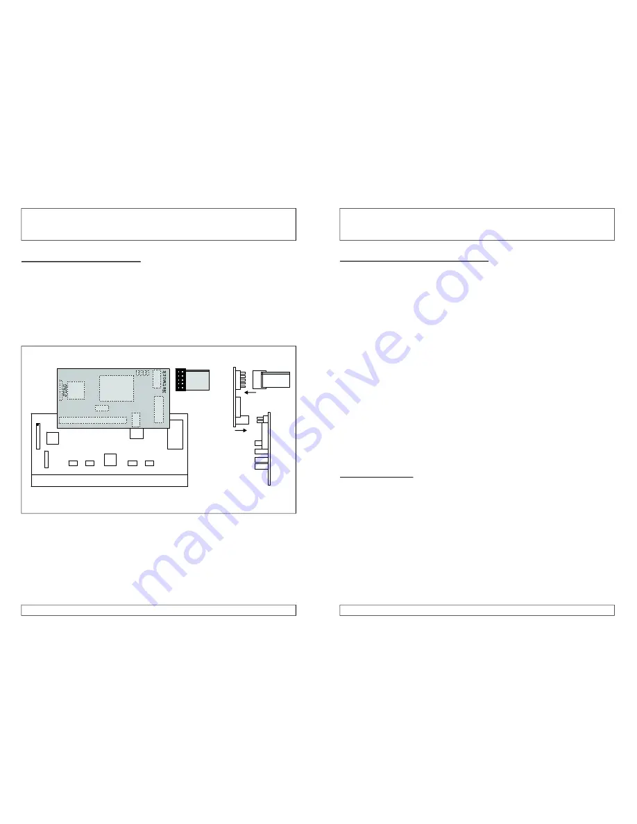
Open your Amiga computer housing (see your computer's manual for
detailed instructions) by removing the holding screws on the back and /
or the sides. Afterwards, the upper part of the housing can easily be
removed.
Remove the
from its Zorro slot and put it on the table,withthe
SMD parts looking upwards. The Zorro connector should face to you,
the USB connector to the right.
HIGHWAY
[Fig. 2] Connection of
and
(top side / front side view).
HIGHWAY
NORWAY
JTAG
Zorro Connector
1
1
Expansion port
Status LEDs
NIC
red cable
The
is now attached to the expansion port of the
with the SMD parts facing downwards.Please check care fully that
both connectors fit perfectly and that
.
Misplacing the
can lead to damages.
Insert the
/
combicard into its Zorro slot.
NORWAY
NORWAY
NORWAY
HIGHWAY
HIGHWAY
no pins are left over on any
side
NORWAY
7
4.4. Connecting the network cable
4.5. Status LEDs
The small size of the
opens many possibilities where to
place the SUBD9 connector carrying the network signals.
Connect the 10pin female connector with the flat ribbon cable (see
figure 2) to the
. The red cable must face away from the
card. Now fix the holding plate in a free slot. You also can
mount this connector in a spare plate position (like in the A4000 CPU
plate on the backside). Place the enclosed sticker “Ethernet” next to
the connector to avoid confusion when connection cables !
The SUBD9 to RJ45 adaptor enclosed in your package is now
connected to the holding plate you just mounted. Fixate the adaptor
with its screws to get a secure connection to the network.
Your twisted pair network cable can directly be connected to the
adaptor. Use a normal, straightforward cable for connections to hubs
or switches. For a direct connection between two computers a
crossover cable is needed. Both cable types should be on stock at your
computer dealer.
Close your computer before reconnecting theAC power cable.
IYour
is equipped with four LEDs which allow control of
network traffic. They are located between the network connector and
the NIC on the
module.
The LEDs show the following signal(left to right):
TX . . . . . . . green . . . . . . . Data transfer to network
RX . . . . . . . green . . . . . . . Data transfer from network
COL . . . . . . red . . . . . . . . . Collision
LNK . . . . . . orange . . . . . . Carrier found
NORWAY
NORWAY
NORWAY
NORWAY
HIGHWAY
NORWAY
Содержание NORWAY
Страница 1: ...Ethernet addon for USB HIGHWAY...


