background image

E2S Warning Signals Impress House, Mansell Road, Acton, London W3 7QH    

[email protected]          e2s.com      

Page 1  of 1

D221-95-001-IS_Issue_A - 09/03/2021

1000Hz PFEER Toxic Gas

1200/500Hz @ 1Hz DIN /PFEER P.T.A.P.

1000Hz @ 0.5Hz(1s on, 1soff) PFEER Gen. Alarm

1.4KHz-1.6KHz 1s, 1.6KHz-1.4KHz 0.5s NF C 48-265

544Hz(100mS)/440Hz (400mS) NF S 32-001

1500/500Hz - (0.5s on , 0.5s off) x3 + 1s gap AS4428

500-1500Hz Sweeping 2 sec on 1 sec off AS4428

500/1200Hz @ 0.26Hz (3.3son, 0.5s off) Netherlands - 

NEN 2575

1000Hz (1s on, 1s off)x7 + (7s on, 1s off) IMO Code 1a

1000Hz (1s on, 1s off)x7 + (7s on, 1s off) IMO Code 1a

420Hz(0.5s on, 0.5s off)x3 + 1s gap ISO 8201 Temporal 

Pattern

1000Hz(0.5s on, 0.5s off)x3 + 1s gap ISO 8201 Temporal 

Pattern

422/775Hz - (0.85 on, 0.5 off) x3 + 1s gap NFPA - 

Temporal Coded

1000/2000Hz @ 1Hz Singapore

300Hz Continuous

440Hz Continuous

470Hz Continuous

500Hz Continuous IMO code 2 (Low)

554Hz Continuous

660Hz Continuous

800Hz IMO code 2 (High)

1200Hz Continuous

2000Hz Continuous 

2400Hz Continuous

440Hz @0.83Hz (50

cycles/minute) Intermittent

470Hz @0.9Hz - 1.1s Intermittent

470Hz @5Hz - (5

cycles/second) Intermittent

544Hz @ 1.14Hz - 0.875s Intermittent

655Hz @ 0.875Hz Intermittent

660Hz @0.28Hz - 1.8sec

on, 1.8sec off Intermittent

660Hz @3.34Hz - 150mS

on, 150mS off Intermittent

745Hz @ 1Hz Intermittent

800Hz - 0.25sec on, 1 sec off Intermittent 

800Hz @ 2Hz IMO code 3.a

(High) Intermittent

1000Hz @ 1Hz Intermittent

2400Hz @ 1Hz Intermittent

2900Hz @ 5Hz Intermittent

363/518Hz @ 1Hz Alternating

450/500Hz @ 2Hz Alternating

554/440Hz @ 1Hz Alternating

554/440Hz @ 0.625Hz Alternating

561/760Hz @0.83Hz (50

cycles/minute) Alternating

800/1000Hz @ 0.875Hz Alternating

2400/2900Hz @ 2Hz Alternating

500/1200Hz @ 0.3Hz Sweeping

560/1055Hz @ 0.18Hz Sweeping

560/1055Hz @ 3.3Hz Sweeping

660/1200Hz @ 1Hz Sweeping

800/1000Hz @ 1Hz Sweeping

800/1000Hz @ 7Hz Sweeping

800/1000Hz @ 50Hz Sweeping

2400/2900Hz @ 7Hz Sweeping

2400/2900Hz @ 1Hz Sweeping

2400/2900Hz @ 50Hz Sweeping

2500/3000Hz @ 2Hz Sweeping

2500/3000Hz @ 7.7Hz Sweeping

800Hz Motor Siren

1200Hz Motor Siren

2400Hz Motor Siren

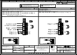
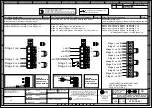
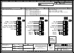
Stage 1

Set DIP

SW 1

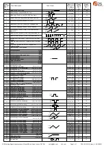
Tone No.

Tone Description

Tone Visual

Stage 1 & 2

DIP SW 1/2

 Settings

1 2 3 4 5 6

Stage 3

Set DIP

SW 1

(S3)

Stage 4

Set DIP

SW 1

(S2 + S3)

0 0 0 0 0 0

1

2

3

4

5

6

7

8

9

10

11

12

13

14

15

16

17

18

19

20

21

22

23

24
25
26
27
28

29
30

31
32

33
34
35

36

37

38

39

40

41

46

47

48

49

50

52

53

54

55

56

57

58

59

60

61

62

63

42

1 0 0 0 0 0

0 1 0 0 0 0

1 1 0 0 0 0

0 0 1 0 0 0

1 0 1 0 0 0

0 1 1 0 0 0

1 1 1 0 0 0

0 0 0 1 0 0

1 0 0 1 0 0

0 1 0 1 0 0

1 1 0 1 0 0

0 0 1 1 0 0

1 0 1 1 0 0

0 1 1 1 0 0

1 1 1 1 0 0

0 0 0 0 1 0

1 0 0 0 1 0

0 1 0 0 1 0

1 1 0 0 1 0

0 0 1 0 1 0

1 0 1 0 1 0

0 1 1 0 1 0

1 1 1 0 1 0

1 1 0 1 1 0

0 0 1 1 1 0

0 1 1 1 1 0

0 0 0 0 0 1

0 1 0 0 0 1

1 1 0 0 0 1

0 0 1 0 0 1

1 0 1 0 0 1

0 1 1 0 0 1

1 1 1 0 0 1 

0 0 0 1 0 1 

0 1 0 1 0 1

1 0 1 1 0 1

0 1 1 1 0 1

1 1 1 1 0 1

0 0 0 0 1 1

1 0 0 0 1 1

0 1 0 0 1 1

1 1 0 0 1 1

0 0 1 0 1 1

1 0 1 0 1 1

0 1 1 0 1 1

1 1 1 0 1 1

0 0 0 1 1 1

1 0 0 1 1 1

0 1 0 1 1 1

1 1 0 1 1 1

0 0 1 1 1 1

1 0 1 1 1 1

0 1 1 1 1 1

0 0 0 1 1 0

1 0 0 1 1 0

0 1 0 1 1 0

1 1 1 1 1 0

1 0 0 0 0 1

1 0 0 1 0 1

1 0 1 1 1 0

1000Hz

1200Hz

500Hz 1s

1000Hz 1s

1s

1600Hz

1400Hz

1s

0.5s

544Hz 0.1s

0.4s

440Hz

0.5s

1500Hz

500Hz

0.5s 0.5s 0.5s 0.5s

1s

2s 1s

3s

0.5s

1500Hz

500Hz

1200Hz

500Hz

1000Hz

1s

1s

1s

1s

1s

1s

1s

1s

1s

1s

1s

1s

1s

1s

7s

7s

420Hz 0.5s

0.5s

0.5s

0.5s

0.5s

1s

1000Hz 0.5s

0.5s

0.5s

0.5s

0.5s

1s

1200Hz

500Hz

0.85 0.5s

0.85 0.5s

0.85

2000Hz

1000Hz

1s

f(Hz)

a(s)

b(s)

(f=440, a=0.6, b=0.6)

(f=470, a=0.55, b=0.55)

(f=470, a=0.1, b=0.1)

(f=470, a=0.43, b=0.44)
(f=655, a=0.57, b=0.57)

(f=660, a=1.8, b=1.8)

(f=660, a=0.15, b=0.15)

(f=745, a=0.5, b=0.5)

(f=800, a=0.25, b=1)

(f=800, a=0.25, b=0.25)

(f=1000, a=0.5, b=0.5)
(f=2400, a=0.5, b=0.5)
(f=2900, a=0.1, b=0.1)

f1(Hz)

a(s)

f(Hz)

f1(Hz)

a(s)

a(s)

f(Hz)

(f=363, f1=518, a=0.1)

(f=450, f1=500, a=0.25)

(f=440, f1=554, a=0.5)
(f=440, f1=554, a=0.8)

(f=561, f1=760, a=0.6)

0 0 1 1 0 1

1 1 0 1 0 1

43

44

45

780/600Hz @ 0.96Hz Alternating

800/1000Hz @ 2Hz Alternating

970/800Hz @ 2Hz Alternating

64

Simulated Bell

1 1 1 1 1 1

f1(Hz)

a(s)

a(s)

f(Hz)

(f=800, f1=1000, a=0.57)

(f=2400, f1=2900, a=0.25)

f1(Hz)

a(s)

a(s)

f(Hz)

(f=800, f1=1000, a=0.25)

f1(Hz)

a(s)

a(s)

f(Hz)

(f=600, f1=780, a=0.52)

f1(Hz)

a(s)

a(s)

f(Hz)

(f=800, f1=970, a=0.25)

(f=500, f1=1200, a=3.34)

(f=560, f1=1055, a=5.47)

(f=560, f1=1055, a=0.3)

f1(Hz)

a(s)

f(Hz)

51

600/1250Hz @ 0.125Hz Sweeping

(f=600, f1=1250, a=8)

f(Hz)

a(s)

(f=800, a=1.6)

(f=1200, a=2)

(f=2400, a=1.7)

1450Hz 0.25s

0.69ms

(f=660, f1=1200, a=1)
(f=800, f1=1000, a=1)

(f=800, f1=1000, a=0.14)
(f=800, f1=1000, a=0.02)

(f=2400, f1=2900, a=0.14)

(f=2400, f1=2900, a=1)

(f=2400, f1=2900, a=0.02)

(f=2500, f1=3000, a=0.5)

(f=2500, f1=3000, a=0.13)

(f=300)
(f=440)
(f=470)
(f=500)
(f=554)
(f=660)
(f=800)

(f=1200)
(f=2000)
(f=2400)

f(Hz)

0.5s

2
3

2

24

19

44

44

24

34

34

1

1

1

3

44
44
44
24

24
24

24
24

24
24
24

24

24

8

8

24

8

24

24

24

24

24

24

24

24

24

24

24

24

24

24

24

24

24

8

8

24

8

21

24

24

24

24

24

24

24

24

24

3

20

44
44

44

1

1

1

1

35

1

1

8

8

8

35

8
8
8
8

8
8

8
8

8

19
19

19

19

19

19

19

19
19

19

19

19

19

19

12

12

12

12

12
12
12

12

12

12

12

12

12
12

12

12

1

1

8

8

8

35

35

35

35

35

f1(Hz)

a(s)

f(Hz)

Содержание GNExS1R Series

Страница 1: ...c 50 60Hz 73mA 80mA 110 105 230Vac 48mA GNExS1FDC024 12Vdc 10 30Vdc 221mA 221mA 115 110 24Vdc 185mA GNExS1FDC048 48Vdc 38 60Vdc 115mA 221mA 115 110 GNExS1FAC230 115Vac 100 260Vac 50 60Hz 73mA 80mA 115 110 230Vac 48mA Max Tone 4 Nom Tone 44 The table shows the input current taken by the various sounders A supply voltage variation of 10 outside the voltage range is permissible The current levels sho...

Страница 2: ...Classification The units can be installed in locations with the following conditions Area Classification Zone 1 Explosive gas air mixture likely to occur in normal operation Zone 2 Explosive gas air mixture not likely to occur in normal operation and if it does it will only exist for a short time Gas Groupings Group IIA Propane Group IIB Ethylene Group IIC Hydrogen and Acetylene Temperature Classi...

Страница 3: ...ible between the cover and base of the sounder enclosure Tighten the M3 grub screw 7 Installation Requirements 7 1 Installation Standards Compliance Warning High voltage may be present risk of electric shock DO NOT open when energised disconnect power before opening The sounder must only be installed by suitably qualified personnel in accordance with the latest issues of the relevant standards ATE...

Страница 4: ...ed in the table below Max Ambient Temperature ºC Model 40 45 50 55 60 65 70 GNExS1 70 75 80 85 90 95 Table 2 Min Ratings of Cables Cable Glands Cable Glands Appropriate cable glands to be customer supplied The cable entries have an M20 x 1 5 6H entry thread Only suitably rated and ATEX IECEx certified cable glands must be used They must be suitable for the type of cable being used and also meet th...

Страница 5: ...nt tones that can be selected independently for the first and second stage alarms The tones are selected by operation of the tone setting DIP switch 1 DIP 2witch 2 see figures 6 and 7 on the PCB for stage 1 and stage 2 respectively Default S2 Tone 1 Default S1 Tone 44 ON 1 OFF 0 Figure 9 DIP switch configuration The sounder can also be switched to sound the third and fourth stage alarm tones The t...

Страница 6: ... 06 005 for AC schematic diagrams 7a AC Single Stage Configuration Default 7b AC Three Four Stage Configuration Default 8 AC Two Stage Voltage Free Activation Configuration Custom K Table 3 Summary of Wiring Options 9 End of Line Monitoring DC Units All DC units have a blocking diode fitted in their supply input lines An end of line monitoring diode or an end of line monitoring resistor can be con...

Страница 7: ...vant standards EN60079 19 IEC60079 19 Explosive atmospheres Equipment repair overhaul and reclamation EN 60079 17 IEC60079 17 Explosive atmospheres Electrical installations inspection and maintenance Flameproof threaded joints and cemented joints are not permitted to be repaired Units must not be opened while an explosive atmosphere is present If opening the unit during maintenance operations a cl...

Страница 8: ...E MONITORING RESISTOR CUSTOMER SUPPLIED 14V MAX SYSTEM 120Ω MIN 2W MIN OR 1KΩ MIN 0 5W MIN 28V MAX SYSTEM 470Ω MIN 2W MIN OR 2 4KΩ MIN 0 5W MIN RECOMMENDED MINIMUM VALUES R1 Stage 1 ve IN Stage 1 ve OUT Common ve IN Common ve OUT Stage 2 ve Stage 1 ve IN Stage 1 ve OUT Common ve IN Common ve OUT Stage 2 ve Stage 3 ve R1 R1 S2 R1 S2 S3 Stage 1 ve IN Stage 1 ve OUT Stage 1 ve IN Stage 1 ve OUT Singl...

Страница 9: ...ve OUT Stage 1 ve OUT Stage 3 ve Stage 1 ve IN H2 H1 Stage 1 ve Stage 1 ve Stage 2 ve Stage 2 ve OF 2 3 R1 S2 S3 R1 S2 R2 OPTIONAL LINE MONITORING RESISTOR CUSTOMER SUPPLIED 14V MAX SYSTEM 120Ω MIN 2W MIN OR 1KΩ MIN 0 5W MIN 28V MAX SYSTEM 470Ω MIN 2W MIN OR 2 4KΩ MIN 0 5W MIN RECOMMENDED MINIMUM VALUES R1 Set H1 H2 to ve switching Three Four Stages Voltage Free 2nd 3rd 4th Stage Activation Config...

Страница 10: ...e 2 ve Stage 2 ve Two Three Stage Voltage Free Activation Configuration Config 5 Customer Set H1 H2 to Negative Switching See Below Power ve ve Stage 1 Connect Stage 1 ve to Common ve Stage 2 Cconnect Stage 2 ve to Common ve Stage 3 Connect both Stage 1 ve Stage 2 ve to Common ve CUSTOM CONFIGURATION CONTACT E2S WHEN ORDERING Cut Link W1 H2 H1 Set H1 H2 to ve switching CUSTOM CONFIGURATION CONTACT...

Страница 11: ...S RAIT B ISARD R N POTTS OF NTS 1 SWITCHES FOR STAGE OPERATION CUSTOMER SUPPLIED 1 Earth Earth Stage 2 Stage 3 Common Live IN Live OUT Neutral IN Neutral OUT Earth Stage 1 Stage 2 Common N N L L E N N L L E C N N L L E C S2 S3 Live IN Live OUT Neutral IN Neutral OUT Stage 1 Live IN Stage 1 Live OUT Stage 1 Neutral IN Stage 1 Neutral OUT Single Stage Configuration Config 1a Stage 1 Apply Power to S...

Страница 12: ... 0 0 0 1 0 1 0 0 0 0 1 1 0 0 0 1 1 1 0 0 0 0 0 0 1 0 0 1 0 0 1 0 0 0 1 0 1 0 0 1 1 0 1 0 0 0 0 1 1 0 0 1 0 1 1 0 0 0 1 1 1 0 0 1 1 1 1 0 0 0 0 0 0 1 0 1 0 0 0 1 0 0 1 0 0 1 0 1 1 0 0 1 0 0 0 1 0 1 0 1 0 1 0 1 0 0 1 1 0 1 0 1 1 1 0 1 0 1 1 0 1 1 0 0 0 1 1 1 0 0 1 1 1 1 0 0 0 0 0 0 1 0 1 0 0 0 1 1 1 0 0 0 1 0 0 1 0 0 1 1 0 1 0 0 1 0 1 1 0 0 1 1 1 1 0 0 1 0 0 0 1 0 1 0 1 0 1 0 1 1 0 1 1 0 1 0 1 1 1 0...

Страница 13: ...dy No 2813 CSA Group Netherlands B V Utrechtseweg 310 6812 AR Arnhem Netherlands Quality Assurance Notification Module D SIRA 05 ATEX M342 Provisions fulfilled by the equipment II 2G Ex db IIB or IIC T3 T4 T5 or T6 Gb Standards applied EN 60079 0 2018 EN 60079 1 2014 A C 2018 Directive 2014 30 EU Electromagnetic Compatibility Directive EMC Standards applied EN 61000 6 1 2007 EN 61000 6 2 2005 EN 6...

Страница 14: ...ate and Place of Issue London 23 12 2020 EU Declaration of Conformity On behalf of European Safety Systems Ltd I declare that on the date the equipment accompanied by this declaration is placed on the market the equipment conforms with all technical and regulatory requirements of the above listed directives regulations and standards This Declaration is issued under the sole responsibility of the m...

Отзывы: