background image

ELECTRONIC SPEED CONTROL (48V)

Page F-28

Repair and Service Manual

Read all of Section B and this section before attempting any procedure. Pay particular attention to all Notes, Cautions and Warnings

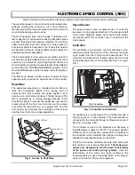
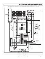
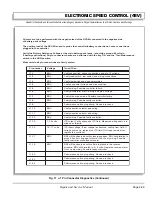
Fig. 10  J-1 Pin Connector Diagnostics

1

2

3

4

5

6

7

8

9

10

11

12

13

14

15

16

17

18

19

20

21

22

23

24

J1

ITS

MS3

Pedal Box 

WHT / YEL

WHT

ORN

ORN

GRN

GRN

GRN / WHT

BLK / WHT

BLU / WHT

GRN / BLK

VIO

YEL

YEL

REV

N

FWD

RED

RED / WHT

RED / WHT

RED / WHT

WHT / BLK

WHT

BLK

BLU

BLK

WHT

SPARE

SPARE

SPARE

SPARE

SPARE

Key
Switch

Direction
Selector
Switch

1264 Controller

F2

B+

M-

B-

F1

Reverse
Buzzer

RED

RED

RED

RED

YEL

RED / YEL

ORN / RED

ORN / RED

Aux

WHT

WHT

Logic

Tow Switch

1

2

3

5

Performance
Plug

Solenoid

Reed
Switch

Charging
Connector

J3

J2

+

4

5

6

1

2

3

BRN

GRY

Содержание MPT 800

Страница 1: ...A Textron Company ELECTRIC POWERED UTILITY VEHICLES REVISED DATE OCT 2006 TECHNICIAN S REPAIR AND SERVICE MANUAL 28838 G01...

Страница 2: ...an normal speeds encountered on a flat surface To pre vent loss of vehicle control and possible serious injury speeds should be limited to no more than the maximum speed on level ground See GENERAL SP...

Страница 3: ...to make these changes on units previously sold and the informa tion contained in this manual is subject to change without notice E Z GO Division of Textron Inc is not liable for errors in this manual...

Страница 4: ...eries will self discharge over time The rate of self discharge varies depending on the ambient temperature and the age and condition of the batteries A fully charged battery will not freeze in winter...

Страница 5: ...Truckbed C Wheels and Tires D Front Suspension and Steering E Electronic Speed Control 36V F 1 Electronic Speed Control 48V F 19 Motor G Batteries and Charging H Electrical System J Brakes Rear Mechan...

Страница 6: ...Page iv Repair and Service Manual TABLE OF CONTENTS Notes...

Страница 7: ...of the material in this manual This vehicle conforms to the current applicable standard for safety and performance requirements These vehicles are designed and manufactured for off road use They do n...

Страница 8: ...ly Always use specified replacement parts Never use replacement parts of lesser quality Always use recommended tools Always determine that tools and procedures not specifically recommended by the manu...

Страница 9: ...anges per hour is considered the minimum requirement Never charge a vehicle in an area that is subject to flame or spark Pay particular attention to natural gas or propane gas water heaters and furnac...

Страница 10: ...Repair and Service Manual SAFETY INFORMATION Page viii Notes...

Страница 11: ...NG THE ELECTRIC VEHICLE A 1 ROUTINE MAINTENANCE A 1 REAR AXLE A 2 BRAKES A 2 TIRES A 2 LIGHT BULB REPLACEMENT A 2 CARE AND CLEANING OF THE VEHICLE A 2 VEHICLE CARE PRODUCTS A 3 TOP AND WINDSHIELD A 3...

Страница 12: ...GENERAL INFORMATION ROUTINE MAINTENANCE Page A ii Repair and Service Manual Notes...

Страница 13: ...e downs SERVICING THE ELECTRIC VEHICLE To prevent severe injury or death resulting from improper servicing tech niques observe the following Warnings Do not attempt any type of servicing operations be...

Страница 14: ...ould be inspected per the Periodic Ser vice Schedule Inflation pressures should be checked when the tires are cool Be sure to reinstall valve dust cap after checking or inflating For additional inform...

Страница 15: ...sealing against future moisture return P N 75503 G01 Multi purpose Cleaner and Degreaser that con tains natural environmentally safe solvents P N 75504 G01 Multi purpose Hand Cleaner is an industrial...

Страница 16: ...TORQUE SPECIFICATIONS Fig 3 Torque Specifications ALL TORQUE FIGURES ARE IN FT LBS Nm BOLT SIZE Grade 2 1 4 5 16 3 8 7 16 1 2 9 16 5 8 3 4 7 8 1 Unless otherwise noted in text tighten all hardware in...

Страница 17: ...lug nuts MONTHLY 20 HOURS includes items listed in previous table the following BATTERIES Clean battery terminals Check charge condition and all connections WIRING Check all wiring for loose connectio...

Страница 18: ...in previous tables the following BATTERIES Clean batteries terminals DIRECTION SELECTOR Check for wear and smooth movement lubricate shaft with light oil if required KING PINS Check for excessive play...

Страница 19: ...UTIONS AND WARNINGS B 5 IMPORTANT SAFETY WARNING B 5 MODIFICATIONS TO VEHICLE B 5 GENERAL MAINTENANCE B 5 BEFORE SERVICING THE VEHICLE B 6 Additional Warnings B 6 BATTERY REMOVAL INSTALLATION B 7 LIFT...

Страница 20: ...SAFETY Page B ii Repair and Service Manual Notes...

Страница 21: ...apacity or safe operation or make any change not in accordance with the owner s manual without the manufacturer s prior written authori zation Where authorized modifications have been made the user sh...

Страница 22: ...those claiming previous experience 5 2 3 The user should include in the operators train ing program the following a instructional material provided by the manufac turer b emphasis on safety of passen...

Страница 23: ...the elevator neutralize the controls shut off power and set parking brakes It is advisable that all other personnel leave the elevator before a carrier is allowed to enter or exit 5 5 13 Avoid runnin...

Страница 24: ...n pans of fuel or flammable cleaning fluids for cleaning parts j Properly ventilate the work area k Handle LP gas cylinders with care Physical dam age such as dents scrapes or gouges may danger ously...

Страница 25: ...u if the compo nent should move unexpectedly Some components are heavy spring loaded highly cor rosive explosive or may produce high amperage or reach high temperatures Battery acid and hydrogen gas c...

Страница 26: ...r cutting the batteries must be removed Additional Warnings Before working on the electrical system be sure to read and understand the following warnings that pertain to electrical system repair or ma...

Страница 27: ...ories are turned OFF Using an insulated wrench remove the negative cable first the positive cable and then all other cables from the vehicle batteries Remove the battery hold down by removing the hard...

Страница 28: ...the vehi cle is on a firm and level surface Never get under a vehicle while it is supported by a jack Use jack stands and test the stability of the vehicle on the stands Always place chocks in front...

Страница 29: ...cate a jack stand under outer ends of rear axle Lower the jack and test the stability of the vehicle on the two jack stands Place the jack at the center of the front axle Raise the vehicle and positio...

Страница 30: ...SAFETY Page B 10 Repair and Service Manual Read all of Section A and this section before attempting any procedure Pay particular attention to all Notes Cautions and Warnings Notes...

Страница 31: ...1 General C 1 BODY COMPONENT REPLACEMENT C 1 LIST OF ILLUSTRATIONS Fig 1 Drill Out Metal Rivet C 1 Fig 2 Body Components Front C 2 Fig 3 Body Components Rear C 3 Fig 4 Battery Rack Components C 4 Fig...

Страница 32: ...BODY Page C ii Repair and Service Manual Notes...

Страница 33: ...ed with a minimum of specialized tools Most body components are held in place with conventional remov able hardware nuts bolts washers and screws Some components are mounted with pop rivets which requ...

Страница 34: ...BODY Page C 2 Repair and Service Manual Read all of Section B and this section before attempting any procedure Pay particular attention to all Notes Cautions and Warnings Fig 2 Body Components Front...

Страница 35: ...DY Page C 3 Repair and Service Manual Read all of Section B and this section before attempting any procedure Pay particular attention to all Notes Cautions and Warnings Fig 3 Body Components Rear 84 8...

Страница 36: ...BODY Page C 4 Repair and Service Manual Read all of Section B and this section before attempting any procedure Pay particular attention to all Notes Cautions and Warnings Fig 4 Battery Rack Components...

Страница 37: ...e C 5 Repair and Service Manual Read all of Section B and this section before attempting any procedure Pay particular attention to all Notes Cautions and Warnings Fig 5 Ashtray and Hitches Vehicle Rea...

Страница 38: ...C 6 Repair and Service Manual Read all of Section B and this section before attempting any procedure Pay particular attention to all Notes Cautions and Warnings Fig 6 Metal Truckbed Part of Truckbed...

Страница 39: ...Y Page C 7 Repair and Service Manual Read all of Section B and this section before attempting any procedure Pay particular attention to all Notes Cautions and Warnings Fig 7 Plastic Truckbed A A B B C...

Страница 40: ...pair and Service Manual Read all of Section B and this section before attempting any procedure Pay particular attention to all Notes Cautions and Warnings Fig 8 Electric Dump Actuator may be rotated 9...

Страница 41: ...NTENTS FOR SECTION D SECTION TITLE PAGE NO Page D i Repair and Service Manual D WHEELS AND TIRES WHEEL AND TIRE SERVICE D 1 Tire Repair D 1 Wheel Installation D 1 LIST OF ILLUSTRATIONS Fig 1 Wheels an...

Страница 42: ...WHEELS AND TIRES Page D ii Repair and Service Manual Notes...

Страница 43: ...higher inflation pressure On very soft turf a lower pressure prevents tires from cutting into the turf For vehicles being used on paved or hard surfaces tire inflation pressure should be in the higher...

Страница 44: ...pair and Service Manual Read all of Section B and this section before attempting any procedure Pay particular attention to all Notes Cautions and Warnings Fig 1 Wheels and Tires Wheel and or Tire styl...

Страница 45: ...15 Steering Wheel Replacement G 16 Steering Shaft and Column Replacement G 17 LIST OF ILLUSTRATIONS Fig 1 Axle Mounted Steering and Front Suspension G 1 Fig 2 Lubrication Points G 2 Fig 3 Bearing Adju...

Страница 46: ...FRONT SUSPENSION AND STEERING Page E ii Repair and Service Manual Notes...

Страница 47: ...rticular attention to all Notes Cautions and Warnings Fig 1 Axle Mounted Steering and Front Suspension Part of Frame Part of Frame Wave Washer Bearing Outer Snap Ring Inner Snap Ring Intermediate Shaf...

Страница 48: ...ion To prevent possible inju ry or death resulting from a vehicle falling from a jack follow the lifting procedure in Section B of this manual Be sure vehicle is on a firm and level surface Never get...

Страница 49: ...t resistance is felt Rotate the wheel 2 3 more turns to displace excess grease If required tighten castellated nut 3 again until slight resistance is felt If the cotter pin hole in the spindle 5 align...

Страница 50: ...right hand threads counter clockwise to loosen To adjust wheel alignment loosen tie rod jam nuts 1 and turn tie rod 2 until correct alignment is achieved Tighten jam nuts to 36 40 ft lbs 49 54 Nm torq...

Страница 51: ...5 Compress shock absorber to clear the mounting bracket Loosen the nut securing the top of the shock absorber to the vehicle frame and then rotate the shock absorber while holding the nut in place wit...

Страница 52: ...d discard lock nuts At the 3 1 2 long bolt 20 securing front of left spring note location of washer 22 and remove it from end of bolt Remove nut 21 3 1 2 long bolt 20 spring plate 24 and spacer 23 and...

Страница 53: ...er side spring must be mounted to the axle with the hardware 20 23 installed in its original location Ref Fig 6 on page E 5 Driver side spring installation is the reverse order of dis assembly making...

Страница 54: ...the two wheel bearings about 1 2 3 4 full with grease and apply a light coating to the outer bearing race Install outer wheel bearing 4 and secure hub loosely with castellated nut Place wheel onto hu...

Страница 55: ...es Cautions and Warnings Install inner wheel bearing 4 and new grease seal in hub and mount hub to spindle See Hub Replacement on page E 8 Adjust bearing See Wheel Bearing Adjust ment on page E 3 Repl...

Страница 56: ...k ball joint 1 loosen passenger side front wheel and lift and support front of vehicle per SAFETY section Ref Fig 12 on page E 10 Remove passenger side front wheel and turn steering wheel fully to the...

Страница 57: ...per SAFETY section Check front wheel alignment and adjust if necessary See Wheel Alignment on page E 3 Tie Rod Inspection Replacement Tool List Qty Required Tape measure 1 Wrench 3 4 1 Wrench 9 16 1 N...

Страница 58: ...lift and support front of vehicle per SAFETY section Remove passenger side front wheel and turn steering wheel fully to the left Remove rack ball joint 2 and jam nut 3 from rack extension 4 See Rack B...

Страница 59: ...not apply grease to the spindle bearings Loosen front wheel Lift and support front of vehicle per SAFETY section and remove front wheel If vehicle is equipped with front disc brakes remove cali per b...

Страница 60: ...rack 3 and pinion 4 Ref Fig 19 on page E 14 Loosen jam nut 5 and remove rack ball joint 6 from rack extension 7 Cut wire ties 8 14 securing bellows 9 and slide bellows off rack extension Pull rack 3...

Страница 61: ...nit to front axle and discard nuts The rack and pinion unit can now be removed from vehicle Retain washers 19 spacers 20 and the two bolts 16 for assembly Replace rack and pinion unit in reverse order...

Страница 62: ...the retaining tabs From the front side of the steering wheel 4 remove the clipboard 5 by first pulling straight up on the bottom of the clipboard to release the two bottom retaining tabs Then using t...

Страница 63: ...bs 1 Wheel bearing grease AR To remove steering shaft 4 Ref Fig 24 on page E 17 remove the steering wheel See Steering Wheel Replacement on page E 16 Loosen front wheels Lift and support front of vehi...

Страница 64: ...Manual Read all of Section B and this section before attempting any procedure Pay particular attention to all Notes Cautions and Warnings Fig 25 Small Retaining Ring Orientation Install with arch up a...

Страница 65: ...ram F 4 Fig 7 Detailed Troubleshooting Diagram Sheet 1 of 8 F 5 Fig 8 Detailed Troubleshooting Diagram Sheet 2 of 8 F 6 Fig 9 Detailed Troubleshooting Diagram Sheet 3 of 8 F 7 Fig 10 Detailed Troubles...

Страница 66: ...ig 3 Controller and Solenoid F 21 Fig 4 Battery Reference Voltage F 23 Fig 5 Continuity Check of Switch F 23 Fig 6 Continuity Check of Solenoid F 24 Fig 7 48 volt Fault Codes F 25 Fig 8 Controller Con...

Страница 67: ...the solenoid terminal with the red wire attached Ref Fig 2 on page F 1 If the diode is incorrectly oriented the pedal box micro switch and the direc tion selector micro switch may be permanently dama...

Страница 68: ...t full throttle for more than 4 5 seconds while vehicle is in a no load condition Raise the rear wheels of the vehicle and support on jack stands Refer to the Lifting Procedure in Section B Safety Tes...

Страница 69: ...ve a continuity setting set it to K the meter will indicate 0 when it detects continuity Testing a Switch for Continuity Place one probe on one contact of the switch place the second probe on the seco...

Страница 70: ...ian and assistants that all warnings and safety procedures in this section be followed Fig 6 Simplified Troubleshooting Diagram Solenoid Click Solenoid Click Yes Yes Yes Key ON Direction Selector in F...

Страница 71: ...of Solenoid No 0 5 2 5 Volts Less Than Reference Voltage Yes Same as Ref Volt START No Voltage Between Battery B Controller B Correct Wiring Problem Between Solenoid Controller B 0 5 2 5 Volts Less Th...

Страница 72: ...erence Voltage Yes Voltage Between Battery B Charger Receptacle Positive Pin Correct Charger Harness Large White Wire Problem Reassemble Reference Voltage Yes No Zero Key ON Direction Selector in F Vo...

Страница 73: ...ON Direction Selector in F Battery B to Back Side of Control Harness 4 Pin Connector Pin With Green Wire Correct Problem In Green Control Harness Wire The 4 pin connector is a very difficult item to...

Страница 74: ...No Outside Range Voltage Between Controller B Controller Pin 2 Verify Controller Pin 2 Connection If Good Replace Controller Reconnect 4 Pin Connect Key ON Direction Selector in F Pedal Fully Depress...

Страница 75: ...B to Back Side of Control Harness 4 Pin Connector Black Wire Pin Disconnect Battery Wire Disconnect 6 Pin Connector from Controller White Wire to ITS Should Already Be Disconnected Continuity Yes Cont...

Страница 76: ...l Fully Depressed Key ON Direction Selector in F No No Voltage No Outside Range Reference Voltage Yes Voltage Between Controller B Controller M Voltage Between Battery B Controller M 5 2 5 Volt Less T...

Страница 77: ...ctor in F Key ON Direction Selector in F No No Voltage Yes Correct Wire Problem Between Direction Selector C Motor A2 No No Voltage Yes Replace Motor 5 2 5 Volt Less Than Reference Voltage 5 2 5 Volt...

Страница 78: ...ed Voltage Between Controller B Controller M No 60 Ref Volt Yes Replace Controller Key ON Direction Selector in F Voltage Between Battery B Controller Orange Wire Reinstall Orange Wire Key ON Directio...

Страница 79: ...ead 1 5 1 7 volts at full pedal Ref Fig 18 on page F 15 If the reading is out of specification the ITS sensor must be replaced The ITS attaches to the plastic pedal box using two plastic studs and two...

Страница 80: ...d Warnings Fig 17 ITS Adjustment Sheet 1 of 2 Use 17 64 drill to measure gap between plunger and ITS Micro switch disengaged Micro switch disengaged Pedal bracket rest against front of pedal frame ope...

Страница 81: ...tion to all Notes Cautions and Warnings Fig 18 ITS Adjustment Sheet 2 of 2 Micro switch activated Plunger enters ITS Plunger fully activated Pedal bracket rests on rear of pedal frame opening 3 4 SOLE...

Страница 82: ...olts to 11 14 ft lbs 15 19 Nm torque Replace the environmental cover and tighten the mount ing bolts to 108 132 in lbs 12 15 Nm torque Reconnect the BL battery cable and replace the seat SOLENOID REPL...

Страница 83: ...B MS2 MS4 RED BLK A2 A1 S1 S2 Motor M_ B _ 1 2 3 4 5 6 A2 B Controller 1206 Solenoid BLK BLK WHT ORN Direction Selector Switch ORN BLK BLK BLK BLK BLK BLK BLK BLK BLK BLK BLK BLK BLK BLK BLK BLK BLK W...

Страница 84: ...LECTRONIC SPEED CONTROL 36V Page F 18 Repair and Service Manual Read all of Section B and this section before attempting any procedure Pay particular attention to all Notes Cautions and Warnings Notes...

Страница 85: ...kph instead of 13 5 mph 22 kph 4 The Red Plug performance option This option includes all of the driving features of the Blue Plug option except that the flat ground and downhill com pression braking...

Страница 86: ...is depressed the electronic brak ing and warning beeper will be overridden and normal vehicle operation resumes Any unusual situation sensed by the 48 volt system will cause a similar response The sy...

Страница 87: ...pedal box remove the rocker panel lift the floor mat and remove the access cover from the floor Ref Fig 2 on page F 21 The ITS and plunger are accessed by removing the four screws and top cover from t...

Страница 88: ...facturer s recommenda tions and instructions for the use and care of the meter To assure accurate readings be sure to set the meter to the closest voltage reading above the expected voltage To prevent...

Страница 89: ...ect Continuity The meter will give an audible signal when it detects continuity If the meter does not have a continuity setting set it to K the meter will indicate 0 when it detects continuity Testing...

Страница 90: ...will assist in servicing the vehi cle By utilizing the Fault Codes considerable time will be saved in determining the probable vehicle operating malfunction The vehicle power and control wiring dia gr...

Страница 91: ...wiring Replace controller 1 2 Throttle Fault 1 Vehicle will not run Check pedal box adjustment connections Replace ITS 1 3 Speed Sensor Fault Vehicle runs slowly Check speed sensor magnet wire sensor...

Страница 92: ...ehicle will not run Replace controller 4 5 Welded auxiliary con tact Vehicle runs slowly Replace controller 5 1 EEprom failsafe Vehicle will not run Replace controller 5 2 Main coil open Vehicle will...

Страница 93: ...x WHT YEL WHT ORN ORN GRN GRN GRN WHT BLK WHT BLU WHT GRN BLK VIO YEL YEL REV N FWD RED RED WHT RED WHT RED WHT WHT BLK WHT BLK BLU BLK WHT BLK WHT RED BLK BLK SPARE SPARE SPARE SPARE SPARE SPARE SPAR...

Страница 94: ...4 15 16 17 18 19 20 21 22 23 24 J1 ITS MS3 Pedal Box WHT YEL WHT ORN ORN GRN GRN GRN WHT BLK WHT BLU WHT GRN BLK VIO YEL YEL REV N FWD RED RED WHT RED WHT RED WHT WHT BLK WHT BLK BLU BLK WHT SPARE SPA...

Страница 95: ...and pin 8 voltage J1 3 BRV Verify tow switch and aux power wiring J1 7 BRV Verify wire connections Possible controller failure J1 8 BRV Verify wiring Possible faulty controller J1 20 Performance optio...

Страница 96: ...VOM connected to the negative side of battery pack voltage The positive lead of the DVOM is used to probe the controller connections Leave connections plugged in the controller Armature will need to b...

Страница 97: ...BRF preferably 48 Volt Perform battery discharge test Verify the chrager process Negative probe on BL and positive probe on battery side of solenoid BRF Verify wire connection quality Positive probe o...

Страница 98: ...5 volts at full pedal Ref Fig 16 on page F 34 If the reading is out of specification the ITS sensor must be replaced The ITS attaches to the plastic pedal box using two plastic studs and two speed nu...

Страница 99: ...d Warnings Fig 15 ITS Adjustment Sheet 1 of 2 Use 7 32 drill to measure gap between plunger and ITS Micro switch disengaged Micro switch disengaged Pedal bracket rest against front of pedal frame open...

Страница 100: ...ll Notes Cautions and Warnings Fig 16 ITS Adjustment Sheet 2 of 2 Micro switch activated Plunger enters ITS Plunger fully activated Pedal bracket rests on rear of pedal frame opening 3 4 SOLENOID ACTI...

Страница 101: ...n lbs 12 15 Nm torque and the M6 F1 and F2 bolts to 80 90 in lbs 9 10 Nm torque and M8 B M B bolts to 120 130 in lbs 14 15 Nm torque Replace controller mount assembly in vehicle Replace and tighten nu...

Страница 102: ...10 White From Motor F1 Power Harness 4 Black From Motor A2 Power Harness 18 Yellow From J1 Pin 5 Control Harness 18 Blue From J1 Pin 17 Control Harness 18 Red From Tow Switch and Reverse Buzzer Contro...

Страница 103: ...Bearing Replacement G 3 Field Coil Replacement G 3 Brush Replacement G 3 Motor Assembly G 4 Motor Tests G 4 Motor Installation G 4 LIST OF ILLUSTRATIONS Fig 1 Disconnect Battery Cable G 1 Fig 2 Mark...

Страница 104: ...MOTOR Page G ii Repair and Service Manual Notes...

Страница 105: ...or Removal Disconnect the negative BL battery cable with an insulated wrench before attempting to remove wires from the motor see safety procedures in SAFETY section of this manual The shorting of mot...

Страница 106: ...rvice Manual Read all of Section B and this section before attempting any procedure Pay particular attention to all Notes Cautions and Warnings Fig 3 Motor Components 15 17 8 11 9 14 12 3 2 48V ONLY 1...

Страница 107: ...eplacement Ref Fig 5 on page G 4 Remove internal snap ring 6 and heat the commutator end cover again Press bearing 7 out from commutator end cover 3 When installing bearing into end cover apply pressu...

Страница 108: ...p ring Ref Fig 3 on page G 2 Motor Tests The motor housing is not available as an individual part No testing is recommended to determine the specific area of failure When a test of the power wiring sy...

Страница 109: ...Notes Cautions and Warnings Fig 6 Motor Wiring 36V Fig 7 Motor Wiring 48V Motor Terminal Wire Marker From A1 A2 S1 S2 A1 A2 S1 S2 Direction Selector B Direction Selector D Controller B Controller A2...

Страница 110: ...MOTOR Page G 6 Repair and Service Manual Read all of Section B and this section before attempting any procedure Pay particular attention to all Notes Cautions and Warnings...

Страница 111: ...ltage H 5 TROUBLESHOOTING H 5 Hydrometer H 6 Using A Hydrometer H 6 BATTERY CHARGER H 7 Description H 7 Portable Charger Installation H 7 Charger Maintenance H 8 LIST OF ILLUSTRATIONS Fig 1 Correct El...

Страница 112: ...BATTERIES AND CHARGING Page H ii Repair and Service Manual Notes...

Страница 113: ...n elec trolyte being expelled from the battery during the charge cycle Expelled elec trolyte may cause damage to the vehicle and storage facility Aerosol containers of battery terminal protectant must...

Страница 114: ...t of the battery vents by the hydrogen gas however this loss is minimal If the battery electrolyte level is too high the electrolyte will block the vent tube and the gas will force it out of the vent...

Страница 115: ...of sodium bicarbonate bak ing soda mixed with 1 quart 1 liter of clear water Ref Fig 4 on page H 3 In addition to the batteries special attention should be paid to metallic components adjacent to the...

Страница 116: ...e to the premature discharge of batteries During periods of storage the batteries will need atten tion to keep them maintained and prevent discharge In high temperatures the chemical reaction is faste...

Страница 117: ...ng driven when the charger plug is inserted in the vehicle charging receptacle AC Voltage Battery charger output is directly related to the input volt age If multiple vehicles are receiving an incompl...

Страница 118: ...icle has been operated Using A Hydrometer 1 Draw electrolyte into the hydrometer several times to permit the thermometer to adjust to the electrolyte temperature and note the reading Examine the color...

Страница 119: ...cle located on the panel underneath the driver seat Ref Fig 10 on page H 8 After inserting the polar ized DC plug wait a few seconds and observe ammeter on charger to make sure it moves indicating tha...

Страница 120: ...n to all Notes Cautions and Warnings Charger Maintenance The charging DC cord is equipped with a polarized con nector which fits into a matching receptacle on the vehi cle The power AC cord is equippe...

Страница 121: ...TROUBLESHOOTING J 1 POWER SUPPLY J 4 ACCESSORY WIRING J 4 LIGHT BULB REPLACEMENT J 4 LIST OF ILLUSTRATIONS Fig 1 DVOM J 1 Fig 2 36 Volt Wiring Diagram J 2 Fig 3 48 Volt Wiring Diagram J 3 Fig 4 Ignit...

Страница 122: ...ELECTRICAL SYSTEM Page J ii Repair and Service Manual Notes...

Страница 123: ...g circuit Example 2 If a problem occurs in the lighting circuit that results in only one of the headlights not working there is no reason to check battery wiring or the fuse since it is obvious that v...

Страница 124: ...witch RED RED RED BRN BLK YEL Turn Signal Switch GRN WHT YEL WHT BLK Flasher YEL BLU WHT BLK BLK BLK BRN WHT BRN WHT WHT RED RED Taillight Taillight YEL BRN GRN Turn Signal Turn Signal 36V RED For veh...

Страница 125: ...Part of Key Switch RED RED RED BRN BLK YEL Turn Signal Switch GRN WHT YEL WHT BLK Flasher YEL BLU WHT BLK BRN BRN BRN WHT BRN WHT WHT RED RED Turn Signal Turn Signal Taillight Taillight YEL BRN GRN D...

Страница 126: ...the side of the fuse block where the green wire is con nected A reading of battery voltage indicates that the green wire is in good condition The green wire supplies power to the entire fuse block 4...

Страница 127: ...ng any procedure Pay particular attention to all Notes Cautions and Warnings Fig 4 Ignition Switch Direction Selector State of Charge Meter RED GRN BLK REVERSE BUZZER DASH MOUNTED DIRECTION SELECTOR S...

Страница 128: ...Read all of Section B and this section before attempting any procedure Pay particular attention to all Notes Cautions and Warnings Fig 5 Horn Fuse Block Hour Meter FLOOR MOUNTED HORN BUTTON HORN Floor...

Страница 129: ...nd Service Manual Read all of Section B and this section before attempting any procedure Pay particular attention to all Notes Cautions and Warnings Fig 6 Turn Signal Headlight Tail Light Rear Fender...

Страница 130: ...ELECTRICAL SYSTEM Page J 8 Repair and Service Manual Read all of Section B and this section before attempting any procedure Pay particular attention to all Notes Cautions and Warnings...

Страница 131: ...rake Cable and Equalizer Assembly Removal and Installation K 18 Compensator Assembly Removal and Installation K 18 Brake Pedal Removal and Installation K 18 Parking Brake Catch Bracket Removal and Ins...

Страница 132: ...Brake Pedal Removal and Installation K 19 Fig 28 Catch Bracket and Latch Arm K 19 Fig 29 Pedal Bumper Adjustment K 20 Fig 30 Parking Brake Release Linkage and Kick Off Cam Removal and Installation K...

Страница 133: ...omponents Unlike automotive hydraulic brakes mechanical brakes depend on the travel of the brake cables to move the brake shoes against the brake drums The travel of the brake cables is governed by th...

Страница 134: ...sate for brake shoe wear and eliminate the need for manual brake shoe adjustment Do not manually adjust the brakes by prying back the adjuster arm and turning the star wheel Permanent damage to adjust...

Страница 135: ...tch arm to move away from the catch bracket The spring loaded Parking Brake pedal returns to its original position releasing the brake Compensator Assembly The compensator assembly contains a spring w...

Страница 136: ...ht Providing free travel is correctly adjusted the clevis pins will not be under tension by the brake cables Test Result Fails 2 out of 3 Fails 2 out of 3 Perform the Periodic Brake Performance Test P...

Страница 137: ...ing Do this by first verifying that some braking function exists Then drive vehicle at slow speed and apply the brakes aggressively As the brakes adjust and stop the vehicle more effectively start dri...

Страница 138: ...ovided that shoes have 06 1 5 mm min material System not adjusted properly Check and adjust per manual End of brake cable loose from anchor brackets Check and repair Cracked brake drum Replace Startin...

Страница 139: ...glazed Check again when shoes are dry Rusted or sticky brake pivot hardware Replace Neither wheel locks Brake system requires complete adjustment Adjust entire system Brake pedal not returning Check f...

Страница 140: ...r brake operation depends on periodic maintenance Brake Pedal and Linkage Inspection 1 Inspect brake pedal return bumper Be sure that the brake pedal is contacting the pedal return bumper when release...

Страница 141: ...s Check clevis pins attaching the brake cables to the brake lever They must be loose when the brake pedal has been released Ref Fig 19 on page K 15 If the clevis pins are not loose but brake pedal fre...

Страница 142: ...MAIN TENANCE section of this manual as an evaluation of braking system performance It is useful as a method of identifying subtle loss of performance over time and as part of troubleshooting a proble...

Страница 143: ...visual inspection and evaluate ped al travel before operating a vehicle to verify some braking function is present The purpose of this test is to attempt to fully expand and release the brake adjuste...

Страница 144: ...econd must also be replaced Use care when handling the adjuster arm Too much force will damage the adjuster and require that both wheel brake assemblies be replaced 6 Visually check the condition and...

Страница 145: ...oked to the adjuster with the hook end facing out The brake shoe springs must be installed with the light spring closest to the adjuster mechanism with the hook installed down through the rear brake s...

Страница 146: ...laced Brake pedal free travel is the distance the pedal travels from rest to the point at which the brake cables start to move the brake levers This should not be confused with the light resistance th...

Страница 147: ...mance is satisfactory Brake Drum Removal and Installation Remove the dust cap 1 to gain access to the castel lated nut 2 and the cotter pin 3 Ref Fig 21 on page K 15 Remove the cotter pin and castella...

Страница 148: ...ervice intervals will vary based on usage ter rain and other conditions It is recommended that wheel brake service be performed periodically on a sample of vehicles within the service fleet to establi...

Страница 149: ...he clevis pin installed from the top down and a new cotter pin Install the brake assembly or backing plate to the axle tube flange Install new hardware locknut should only be used once and tighten to...

Страница 150: ...as a complete assembly Remove the cotter pins and clevis pins connecting the brake cables to the brake levers Remove the retaining rings connecting the brake cables to their brackets at the axle rear...

Страница 151: ...edal release mechanism To prevent serious injury death resulting from the use of worn parking brake components to not attempt to re new worn components The catch bracket is a hardened part Do not grin...

Страница 152: ...pin 2 washers 3 and bushings 4 from linkage rod 1 Remove the linkage rod Ref Fig 30 on page K 20 Inspect the bushings 4 If they are worn replace them with new ones Installation is in the reverse order...

Страница 153: ...ster cylinder Remove the bolts securing the brake actuator assembly housing cover and remove cover The clevis pin joining the brake cylinder clevis and the upper actuator pivot must be removed by remo...

Страница 154: ...torque NOTE Unless fluid is lost or a brake line is disconnected there is no need to bleed the system Rotor Replacement The rotor disc brake hub is not designed to be trued turned If the rotor has de...

Страница 155: ...and top off with standard automotive DOT 3 brake fluid Never reuse any excess fluid or return to the orig inal container Dispose of brake fluid properly Brake fluid should never be returned to the ori...

Страница 156: ...BRAKES FRONT DISC Page K 24 Repair and Service Manual Read all of Section B and this section before attempting any procedure Pay particular attention to all Notes Cautions and Warnings Notes...

Страница 157: ...D CHARGER L 2 UNDERSTANDING THE CHARGER L 2 OPENING THE CHARGER L 2 TROUBLESHOOTING L 3 Continuity Checks L 3 Diode Test Procedure L 3 COMPONENT REPLACEMENT L 3 LIST OF ILLUSTRATIONS Fig 1 Charger Ins...

Страница 158: ...BATTERY CHARGER Page L ii Repair and Service Manual Notes...

Страница 159: ...charger off PORTABLE CHARGER INSTALLATION Portable chargers should be mounted on a plat form above the ground or in such a manner as to permit the maximum air flow underneath and around the charger Do...

Страница 160: ...ari ous ways If the charger is disconnected from the vehicle dur ing the charge cycle it will shut off immediately If the AC power is interrupted the charge cycle will continue normally for the remain...

Страница 161: ...gnal when it detects continu ity If the meter does not have a continuity setting set the meter then to K ohms the meter will indicate 0 when continuity is detected Ref Fig 5 on page L 3 Diode Test Pro...

Страница 162: ...Damage Finish Fuse Continuity Check Replace Diode s Go to START Replace Fuse Go to START Repair or Replace Go to START Replace Transformer Replace Capacitor Go to START Diode Check See Diode Test Pro...

Страница 163: ...before attempting any procedure Pay particular attention to all Notes Cautions and Warnings Fig 7 Diode Test Procedure Low Resistance High Resistance Reverse Bias Select Forward Bias DVOM s shown are...

Страница 164: ...Return Ammeter _ WHT BLK Fuse Transformer Capacitor GRN Com No BRN ORN WHT XF Relay Diode Diode Battery Battery Heat Sink Portable Charger C1 C2 S1 S2 S3 S4 P1 P2 Relay Relay Power Input Board AC Inpu...

Страница 165: ...E NO Page M i Repair and Service Manual M REAR SUSPENSION REAR SUSPENSION M 1 GENERAL M 1 Shock Absorber Removal M 1 Shock Absorber Installation M 1 Rear Spring Removal M 1 Rear Spring Installation M...

Страница 166: ...REAR SUSPENSION Page M ii Repair and Service Manual Notes...

Страница 167: ...e with the instructions provided in Section B SAFETY of this manual and support the rear of the vehicle on the outer ends of the rear bumper Remove the bottom shock absorber vinyl cap 1 nut 2 Ref Fig...

Страница 168: ...2 Repair and Service Manual Read all of Section B and this section before attempting any procedure Pay particular attention to all Notes Cautions and Warnings Fig 1 Rear Suspension 8 4 5 6 7 6 7 7 6 7...

Страница 169: ...ft Seal Removal and Replacement N 2 Axle Shaft Replacement N 3 LIST OF ILLUSTRATIONS Fig 1 Motor Wiring 36 Volt N 1 Fig 2 Motor Wiring 48 Volt N 1 Fig 3 Removing Installing Outer Snap Ring N 2 Fig 4 R...

Страница 170: ...REAR AXLE Page N ii Repair and Service Manual Notes...

Страница 171: ...ved If no hoist is available the motor may be held in position by a second person With the springs removed both persons can lift the entire assembly from the jack stands and lower it to the floor Rear...

Страница 172: ...ressure to the threaded end of the axle shaft Ref Fig 5 on page N 2 Axle Shaft Seal Removal and Replacement Tools List Qty Required Internal snap ring pliers 1 Seal puller 1 Seal installer P N 18739 G...

Страница 173: ...a commercially available anti seize compound Install the brake hub and drum thrust washer nut and new cotter pin Ref Fig 9 on page N 3 Tighten the castellated axle nut to 70 ft lbs 95 Nm torque minimu...

Страница 174: ...REAR AXLE Page N 4 Repair and Service Manual Read all of Section B and this section before attempting any procedure Pay particular attention to all Notes Cautions and Warnings...

Страница 175: ...Manual P WEATHER PROTECTION TOP AND WINDSHIELD P 1 Trailering P 1 SUN TOP P 1 Rear Support Installation P 1 Front Strut P 1 Sun Top P 1 SPLIT WINDSHIELD P 3 ONE PIECE WINDSHIELD P 3 LIST OF ILLUSTRAT...

Страница 176: ...WEATHER PROTECTION Page P ii Repair and Service Manual Notes...

Страница 177: ...ear strut item 2 Ref Fig 1 on page P 2 2 Place washer item 3 onto bolt item 4 and insert bolt just through the top hole in the seat back support 3 4 threads 3 Insert rear strut item 2 in the seat back...

Страница 178: ...ll of Section B and this section before attempting any procedure Pay particular attention to all Notes Cautions and Warnings Fig 1 Sun Top 17 Front of Vehicle REAR Front of Vehicle FRONT Front of Vehi...

Страница 179: ...posite side of windshield Swing the top section of windshield up and secure by hooking the top grip on each side of windshield around the strut To secure windshield when lowered press edge of wind shi...

Страница 180: ...P 4 Repair and Service Manual Read all of Section B and this section before attempting any procedure Pay particular attention to all Notes Cautions and Warnings Fig 3 One Piece Windshield 6 5 Strut 3...

Страница 181: ...TABLE OF CONTENTS FOR SECTION Q SECTION TITLE PAGE NO Page Q i Repair and Service Manual Q PAINT PAINTING Q 1 Minor Scratches Q 1 Larger Scratches Q 1 Complete Panel Repair Q 1...

Страница 182: ...PAINT Page Q ii Repair and Service Manual Notes...

Страница 183: ...lean the surface to be repaired with alcohol and dry II Mask the area to be painted common masking tape is adequate prior to repair and use aerosol type touch up paint III Apply spray touch up paint i...

Страница 184: ...PAINT Page Q 2 Repair and Service Manual Read all of Section B and this section before attempting any procedure Pay particular attention to all Notes Cautions and Warnings Notes...

Страница 185: ...R SECTION TITLE PAGE NO Page R i Repair and Service Manual R TROUBLESHOOTING ELECTRICAL SYSTEM R 1 Basic Electrical Power System Troubleshooting R 2 Basic Electrical Troubleshooting for Accessories R...

Страница 186: ...TROUBLESHOOTING Page R ii Repair and Service Manual Notes...

Страница 187: ...tion switch or motor Repair or replace faulty wiring Solenoid has failed Replace solenoid Key switch has failed Replace key switch Micro switch at direction selector switch has failed Replace micro sw...

Страница 188: ...tion or the ELECTRONIC SPEED CON TROL 48 VOLT section Basic Electrical Troubleshooting for Accessories To diagnose elecrical problems in the vehicle electrical wiring system refer to the ELECTRICAL SY...

Страница 189: ...ck Any distortion of the bellows may indicate that an excess of grease has built up in the bellows Remove the bellows and remove excess grease Insufficient lubricant in king pins rod ends idler bushin...

Страница 190: ...pting any procedure Pay particular attention to all Notes Cautions and Warnings STEERING PULLS TO ONE SIDE Incorrect tire pressure Inflate to recommended pressure Dragging wheel brake Service brake sy...

Страница 191: ...ING Grounding Requirements S 1 Ground Systems S 1 Lightning Protection Requirements S 1 Equipment Fault and Personal Safety System S 1 Ground Network Requirements S 1 External Grounding Requirements S...

Страница 192: ...LIGHTNING PROTECTION AND GROUNDING Page S ii Repair and Service Manual Notes...

Страница 193: ...annot be obtained due to high soil resistivity rock formations or other abnormal conditions alternate methods for reducing the resistance to earth must be considered Chemical Treatments No salt coke o...

Страница 194: ...ter of the struc ture Ground Loop Conductor In no case shall the ground loop conductor be smaller than a 2 0 AWG bare stranded soft drawn copper wire The ground loop must be installed at least 24 belo...

Страница 195: ...with the AC power distribution conductors There shall be no green wires spliced within the conduit All splices shall be performed at the appropriate junction boxes Bond the ground conductor to all pu...

Страница 196: ...ISION A SUPERCEDES TITLE General Specification Lightning Protection and Grounding Rev ECN 027194 LIGHTNING PROTECTION AND GROUNDING Read all of Section B and this section before attempting any procedu...

Страница 197: ...T 1000 T 2 INDUSTRIAL 800 T 3 INDUSTRIAL 1000 T 4 Commander 280 T 5 Commander 2100 T 6 Jacobsen Hauler 800 T 7 Jacobsen Hauler 1000 T 8 LIST OF ILLUSTRATIONS Fig 1 Vehicle Dimensions T 9 Fig 2 Vehicle...

Страница 198: ...GENERAL SPECIFICATIONS Page T ii Repair and Service Manual Notes...

Страница 199: ...park brake with automatic parking brake release accelerator kick off FRONT SUSPENSION Heavy duty leaf springs with hydraulic shock absorbers REAR SUSPENSION Heavy duty leaf springs with hydraulic sho...

Страница 200: ...clipboard BRAKES Dual rear wheel mechanical self adjusting drum brakes Combination service park brake with automatic parking brake release accelerator kick off FRONT SUSPENSION Heavy duty leaf springs...

Страница 201: ...justing drum brakes Combination service park brake with automatic parking brake release accelerator kick off FRONT SUSPENSION Heavy duty leaf springs with hydraulic shock absorbers REAR SUSPENSION Hea...

Страница 202: ...AKES Dual rear wheel mechanical self adjusting drum brakes Combination service park brake with automatic parking brake release accelerator kick off FRONT SUSPENSION Heavy duty leaf springs with hydrau...

Страница 203: ...ce park brake with automatic parking brake release accelerator kick off FRONT SUSPENSION Heavy duty leaf springs with hydraulic shock absorbers REAR SUSPENSION Heavy duty leaf springs with hydraulic s...

Страница 204: ...BRAKES Dual rear wheel mechanical self adjusting drum brakes Combination service park brake with automatic parking brake release accelerator kick off FRONT SUSPENSION Heavy duty leaf springs with hydr...

Страница 205: ...rvice park brake with automatic parking brake release accelerator kick off FRONT SUSPENSION Heavy duty leaf springs with hydraulic shock absorbers REAR SUSPENSION Heavy duty leaf springs with hydrauli...

Страница 206: ...with clipboard BRAKES Dual rear wheel mechanical self adjusting drum brakes Combination service park brake with automatic parking brake release accelerator kick off FRONT SUSPENSION Heavy duty leaf s...

Страница 207: ...N 280 JACOBSEN 800 MPT 1000 INDUSTRIAL 1000 CUSHMAN 2100 JACOBSEN 1000 103 in 262 cm Rear 38 in 97 cm Front 38 in 97 cm 35 in 89 cm 10 in 25 cm 47 in 119 cm 47 in 119 cm 66 in 168 cm 111 in 282 cm 11...

Страница 208: ...earance Diameter RECOMMENDED MAX RAMP GRADE 25 or 14o MAX RECOMMENDED MAX SIDE TILT 25 or 14o MAX TURNING CLEARANCE DIAMETER MPT 800 19 ft 5 8 m MPT 1000 22 ft 6 7 m INDUSTRIAL 800 19 ft 5 8 m INDUSTR...

Страница 209: ...Portable Battery Charger Dimensions Sized for 3 16 in 5 mm Bolt REAR SIDE 10 ft DC Cord 3 m FRONT 9 1 8 in 23 cm 2 1 4 in 6 cm 7 3 4 in 20 cm 10 7 8 in 28 cm 6 3 4 in 17 cm 4 7 8 in 12 cm 8 3 16 in 21...

Страница 210: ...Page T 12 Repair and Service Manual GENERAL SPECIFICATIONS...

Страница 211: ...omponents will eventually fail to perform properly as the result of normal use age wear or abuse It is virtually impossible to anticipate all possible compo nent failures or the manner in which each c...

Страница 212: ...cal Communications Department E Z GO Division Of Textron Inc 1451 Marvin Griffin Road Augusta Georgia USA 30906 3852 TO CONTACT US North America Technical Assistance Warranty Phone 1 800 774 3946 FAX...

Отзывы: