


ELECTRONIC SPEED CONTROL (36V)
Page F-13
Repair and Service Manual
Read all of Section B and this section before attempting any procedure. Pay particular attention to all Notes, Cautions and Warnings
INDUCTIVE THROTTLE SENSOR (ITS)
TESTING AND REPLACEMENT
Tool List
Qty. Required
Phillips screwdriver ..................................................... 1
Wrench, 7/16" ............................................................. 1
Nut driver, 7/16" .......................................................... 1
Drill bit, 17/64"............................................................. 1
DVOM ......................................................................... 1
Raise the rear wheels of the vehicle and support the
vehicle on jack stands (Refer to Lifting Procedure in Sec-
tion ‘B’ Safety). Test the vehicle stability before proceed-
ing.
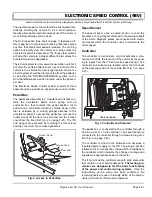
Remove the driver’s side rocker panel insert and pull the
floormat forward to expose the metal cover to the pedal
box (Ref Fig. 15 on page F-13).
Remove the cover and remove the four screws securing
the plastic cover to the pedal box (Ref Fig. 16 on page F-
13).
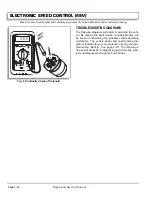
Set the parking ‘PARK’ brake. With the DVOM set to
volts, probe the white wire at the ITS with the positive
probe and attach the negative probe to the B- at battery.
Place the direction selector in ‘F’ and turn the key switch
to ‘ON’. Depress the accelerator pedal. As the solenoid
clicks the meter should read between 0.4 - 0.6 volts. The
meter should read 1.5 - 1.7 volts at full pedal (Ref Fig. 18
on page F-15). If the reading is out of specification, the
ITS sensor must be replaced.
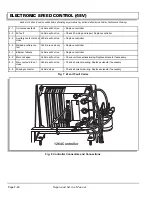
The ‘ITS’ attaches to the plastic pedal
box using two plastic studs and two
speed nuts. Use care not to overtighten the nuts which could
strip the plastic studs while tightening the nuts enough to pre-
vent movement of the ‘ITS’.
Carefully remove the two wires that attach to the ITS and
carefully remove the nuts securing the ITS to the plastic
pedal box studs.
Install a new ITS being careful to align the ITS and not to
overtighten the retaining nuts. Attach the wiring.
With the accelerator pedal in the full up position, insert a
17/64" drill bit between the plunger and the face of the
ITS. The drill bit should be used to verify and adjust the
distance between the face of the ITS and the face of the
plunger (Ref Fig. 17 on page F-14). If the plunger
needs adjustment, loosen the lock nut and rotate the
plunger until the desired dimension is achieved. Firmly
tighten the jam nut.
Replace the plastic cover and press it firmly into place
before tightening the cover screws.
Replace the metal cover, floormat and rocker panel
insert.
Fig. 15 Access to Pedal Box
Rocker Panel
Floor Mat
Access Cover
Pedal Box
PAR
K
Fig. 16 ITS and Plunger
Micro Switch
'ITS'
Connector
Plunger
Micro Switch
Adjusting Cam
Lock Nut
Содержание MPT 800
Страница 6: ...Page iv Repair and Service Manual TABLE OF CONTENTS Notes...
Страница 10: ...Repair and Service Manual SAFETY INFORMATION Page viii Notes...
Страница 12: ...GENERAL INFORMATION ROUTINE MAINTENANCE Page A ii Repair and Service Manual Notes...
Страница 20: ...SAFETY Page B ii Repair and Service Manual Notes...
Страница 32: ...BODY Page C ii Repair and Service Manual Notes...
Страница 42: ...WHEELS AND TIRES Page D ii Repair and Service Manual Notes...
Страница 46: ...FRONT SUSPENSION AND STEERING Page E ii Repair and Service Manual Notes...
Страница 104: ...MOTOR Page G ii Repair and Service Manual Notes...
Страница 112: ...BATTERIES AND CHARGING Page H ii Repair and Service Manual Notes...
Страница 122: ...ELECTRICAL SYSTEM Page J ii Repair and Service Manual Notes...
Страница 158: ...BATTERY CHARGER Page L ii Repair and Service Manual Notes...
Страница 166: ...REAR SUSPENSION Page M ii Repair and Service Manual Notes...
Страница 170: ...REAR AXLE Page N ii Repair and Service Manual Notes...
Страница 176: ...WEATHER PROTECTION Page P ii Repair and Service Manual Notes...
Страница 182: ...PAINT Page Q ii Repair and Service Manual Notes...
Страница 186: ...TROUBLESHOOTING Page R ii Repair and Service Manual Notes...
Страница 192: ...LIGHTNING PROTECTION AND GROUNDING Page S ii Repair and Service Manual Notes...
Страница 198: ...GENERAL SPECIFICATIONS Page T ii Repair and Service Manual Notes...
Страница 210: ...Page T 12 Repair and Service Manual GENERAL SPECIFICATIONS...


