


SHANGHAI ESURVEY GNSS CO., LTD.
94
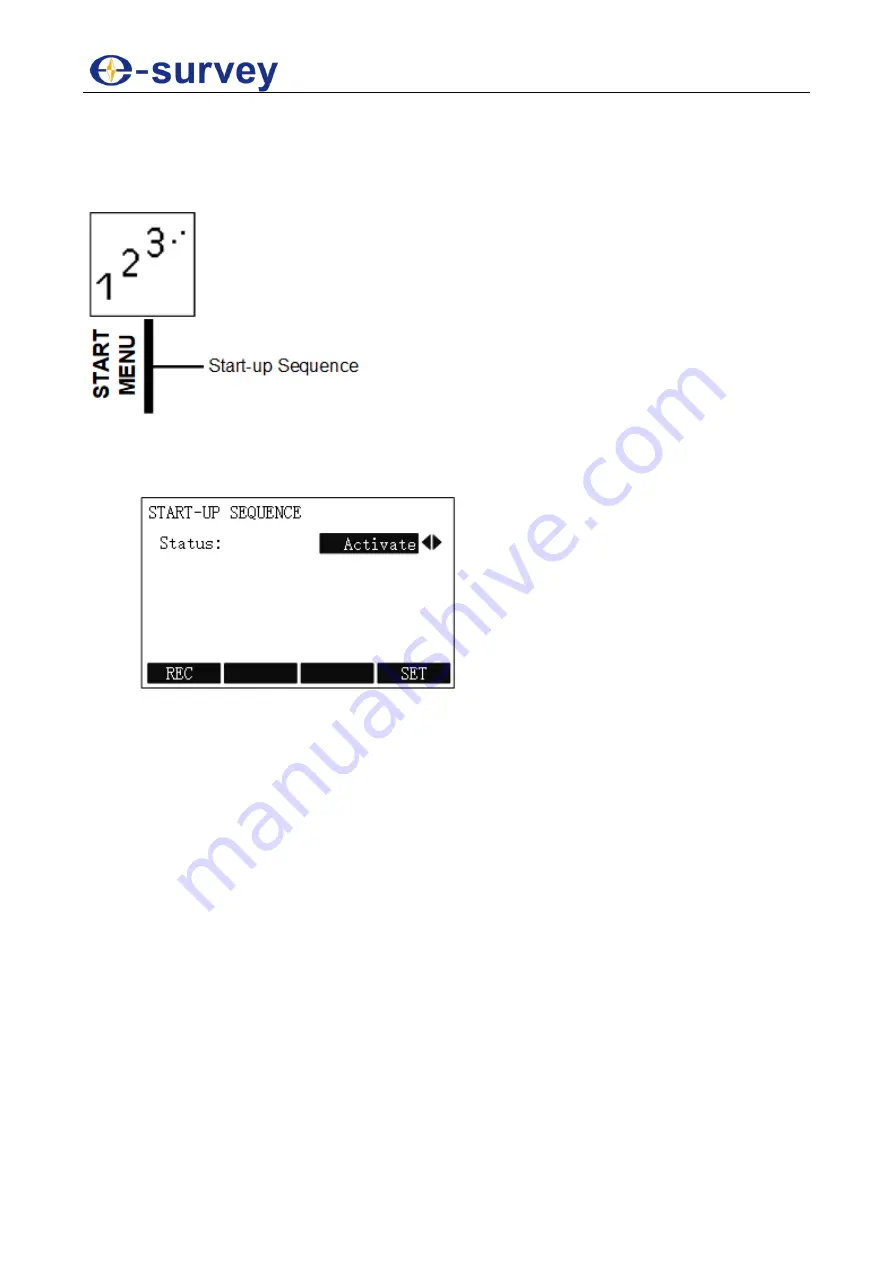
5.9 Start Menu
It is used to set the start-up sequence.
With this menu, you can achieve the following:
To set the start-up sequence, do the following:
1. To enter
START-UP SEQUENCE
display, press
MENU
, press
PAGE
to go to the
second page, and press
F4 START
/
8
:
2. Select the status.
3. To give the definition that start-up sequence will be executed automatically on
triggering the key, press
F1 REC
.
4. To store the current settings, press
F4 SET
.
Содержание E3L
Страница 1: ...Shanghai eSurvey GNSS Co Ltd 1st Edition V1 1 E3L USER GUIDE TOTAL STATION...
Страница 2: ......
Страница 4: ...SHANGHAI ESURVEY GNSS CO LTD...
Страница 10: ...SHANGHAI ESURVEY GNSS CO LTD VI...
Страница 40: ...SHANGHAI ESURVEY GNSS CO LTD 30 Orthogonal Stake out The principle is as follows...
Страница 115: ......


