background image

Hawker Sea Fury 480 ARF

Assembly Manual

Содержание Hawker Sea Fury 480

Страница 1: ...Hawker Sea Fury 480 ARF Assembly Manual ...

Страница 2: ...ation Not for Children under 14 years This is not a toy Components Use only with compatible components Should any compatibility questions exist please refer to the product instructions the component instructions or contact Horizon Hobby Inc Flight Fly only in open areas to ensure safety It is recommended flying be done at AMA Academy of Model Aeronautics approved flying sites Consult local laws an...

Страница 3: ...ury was on August 9 1952 when Lieutenant Peter Hoagy Carmichael of the Royal Navy shot down a MiG 15 jet powered fighter in combat This was one of very few piston engine powered fighters to successfully engage a turbine powered adversary The E flite Hawker Sea Fury 480 ARF has since been reproduced to offer a lightweight durable and easily repairable Z Foam construction that comes complete with ac...

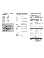
Страница 4: ... tipped pen Hex wrench 1 5mm Hobby knife 11 blades Medium CA Pin drill Razor saw Ruler Sandpaper Thin CA Drill bit 1 16 inch 1 5mm 1 8 inch 3mm Phillips screwdriver 00 0 1 Important Information About Motor Selection We recommend the E flite Park 450 Brushless Outrunner Motor 890Kv EFLM1400 for sport performance or the E flite Park 480 Brushless Outrunner Motor 1020Kv EFLM1505 for maximum performan...

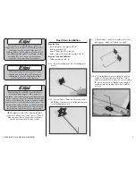
Страница 5: ...articular model We also recommend binding the transmitter and receiver at this time following the instructions provided with your radio system We highly recommend re binding the radio system once all the control throws are set This will keep the servos from moving to their endpoints until the transmitter and receiver connect Fixed Gear Installation Required Parts Fixed main gear wire right and lef...

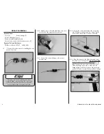
Страница 6: ...ion or your retracts may not operate correctly m 2 Apply a piece of double sided tape onto each servo on the side opposite the servo arm m 3 Connect the retract linkage to the retract actuator arm m 4 Secure the retract assembly in the wing using a 1 Phillips screwdriver and four 3mm x 6mm countersunk sheet metal screws per assembly m 5 Place the retract in the UP position and insert the retract s...

Страница 7: ...nnel or more computer radio you can use a separate channel for each of the retract servos Using two channels and mixing them together will give you the option for independent adjustment of the travel adjustment of each servo If you are not using a computer radio with mixing you will need to use a reversing Y harness EXRA320 instead m 8 Repeat Steps 2 through 7 to install the remaining retract and ...

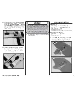
Страница 8: ...ron and the outboard side off the wing Press each aileron servo into the openings in the wing 5 Connect a 6 inch 152mm extension to each aileron servo lead If you have opted to install retracts attach a 9 inch 228mm extension to each retract servo lead Use string to secure the extension s so they do not unplug accidentally 6 Route the leads for the aileron and retract servo s along the channel in ...

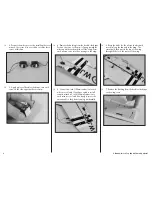
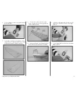
Страница 9: ...r hole of the aileron servo horn m 11 Connect the clevis of the aileron linkage to the aileron control horn With the radio on it may be necessary to adjust the length of the linkage so the aileron is centered 12 Repeat Steps 9 through 11 to connect the remaining aileron linkage Main Wheel Installation Required Parts Wheel spacer 2 Main wheel 2 Wheel axle cap 2 Required Tools and Adhesives Medium C...

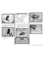
Страница 10: ... 10mm self tapping screw 6 inch 152mm battery extension 3mm x 10mm machine screw 4 Required Tools and Adhesives Razor saw Phillips screwdriver 00 1 1 Attach the Park 450 motor to the mount using a 1 Phillips screwdriver and four 3mm x 10mm machine screws and the four 1 8 inch 3mm spacers as shown Use threadlock on the screws to prevent the vibrations of the motor from loosening the screws Park 450...

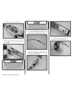
Страница 11: ...rectly for the batteries you are using Never check the motor rotation on the bench with the propeller installed The plane could move and cause serious injury Always check the motor without the propeller to avoid injury 5 Connect the battery and servo lead extensions to the speed control Secure them using string to prevent them from being unplugged inside the fuselage 6 Pass the battery and servo e...

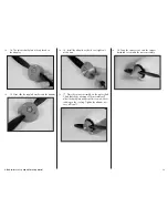
Страница 12: ... the aircraft If not follow the instructions provided with your speed control to correct the situation 11 Remove the backing from the double sided tape on both sides of the fuselage 12 Slide the cowling onto the fuselage Press the cowling against the tape to secure it in position Always balance your propeller An unbalanced propeller can cause vibrations to be transmitted into the airframe which co...

Страница 13: ...r 16 Install the adapter nut but do not tighten it at this time 17 Place the spinner assembly on the motor shaft Check that the positioning of the assembly will allow the backplate and propeller to spin without rubbing on the cowling Tighten the adapter nut once all is well 18 Snap the spinner cone onto the spinner backplate to complete the motor assembly ...

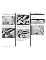
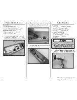
Страница 14: ...2mm extensions for the ailerons to the receiver 3 Use double sided tape to secure the receiver in the fuselage as shown Rudder Preparation Required Parts Control horn Control horn backplate 2mm x 10mm sheet metal screw 2 Operational tail gear wire Tail wheel Wheel spacer Wheel axle cap Required Tools and Adhesives Hobby knife Thin CA Drill bit 1 8 inch 3mm Pin drill Felt tipped pen Sandpaper Mediu...

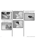
Страница 15: ...ate and a 1 Phillips screwdriver 4 Cut slots in the rudder for the three rudder hinges Use thin CA to glue the hinges half way into the rudder as shown 5 Use a pin drill and 1 8 inch 3mm drill bit to drill a hole for the tail gear wire in the rudder 6 Hold the rudder against the fin and use a felt tipped pen to transfer the location of the hinges to the fin 7 Use a hobby knife to cut the slots for...

Страница 16: ... thin CA on the hinges and tail gear wire to secure the rudder to the fin Make sure not to get CA in the tail gear assembly 10 Slide the wheel spacer onto the tail gear wire 11 Slide the tail wheel onto the tail gear wire 12 Secure the wheel using the wheel axle cap and medium CA Use care not to get CA between the tail gear wire and wheel which will prevent the wheel from rolling ...

Страница 17: ...om each stabilizer tip to each wing tip The measurements must be equal If necessary adjust the position of the stabilizer to correct for the alignment 4 Stand back and view the model from the rear The wing and stabilizer must be parallel to each other Lightly sand the opening in the fuselage for the stabilizer to correct for any alignment issues 5 After aligning the stabilizer to the wing use medi...

Страница 18: ...h 335mm pushrod Slide the pushrod into the preinstalled tube in the fuselage 9 Connect the bend in the pushrod to the elevator servo horn Position the horn so the angle between it and the servo is 90 degrees Secure the horn to the servo 10 Thread the clevis back on the pushrod wire Connect the clevis to the elevator control horn 11 With the radio system on adjust the position of the clevis so the ...

Страница 19: ... control horn 14 With the radio system on adjust the position of the clevis so the rudder is parallel to the fin Final Assembly Required Parts Rocket 6 3mm x 45mm machine screw 2 Battery stop Canopy Required Tools and Adhesives Phillips screwdriver 1 1 Connect the aileron servo extensions to the aileron servos The retract leads will pass into the fuselage and connect to the receiver with a reversi...

Страница 20: ... Make sure to be clear of the propeller when connecting the battery in case the motor starts unexpectedly 5 Slide the battery stop back into the fuselage If it is not fully in position the canopy will not fit back onto the fuselage 6 Place the canopy back onto the fuselage 7 The rockets are installed by pressing them into the precut slots in the wing cover and into the slots in the wing ...

Страница 21: ...movement of the ailerons with the radio system Moving the aileron stick right makes the right aileron move up and the left aileron move down 4 Use a ruler to adjust the throw of the elevator ailerons and rudder Adjust the position of the pushrod at the control horn to achieve the following measurements when moving the sticks to their endpoints Measurements are taken at the widest point on the surf...

Страница 22: ...eed control 3 As you move the controls watch to be sure the airplane s motor and controls operate smoothly You should have total control of the model at 30 paces 90 feet 4 If control issues exist call the appropriate Horizon Product Support office see addresses listed in the Warranty Services section of this manual or go to horizonhobby com to find a local Spektrum distributor in your country for ...

Страница 23: ...WITHOUT LIMITATION THE IMPLIED WARRANTIES OF NON INFRINGEMENT MERCHANTABILITY AND FITNESS FOR A PARTICULAR PURPOSE THE PURCHASER ACKNOWLEDGES THAT THEY ALONE HAVE DETERMINED THAT THE PRODUCT WILL SUITABLY MEET THE REQUIREMENTS OF THE PURCHASER S INTENDED USE Purchaser s Remedy Horizon s sole obligation and purchaser s sole and exclusive remedy shall be that Horizon will at its option either i serv...

Страница 24: ...RMA number are clearly written on the outside of the shipping carton Notice Do not ship LiPo batteries to Horizon If you have any issue with a LiPo battery please contact the appropriate Horizon Product Support office Warranty Requirements For Warranty consideration you must include your original sales receipt verifying the proof of purchase date Provided warranty conditions have been met your Pro...

Страница 25: ...ent 520 A f Ensure the aircraft is identified with the name and address or AMA number of the owner on the inside or affixed to the outside of the model aircraft This does not apply to model aircraft flown indoors g Not operate aircraft with metal blade propellers or with gaseous boosts except for helicopters operated under the provisions of AMA Document 555 h Not operate model aircraft while under...

Страница 26: ... striking an individual This does not apply to model aircraft flown indoors 8 RC night flying requires a lighting system providing the pilot with a clear view of the model s attitude and orientation at all times 9 The pilot of a RC model aircraft shall a Maintain control during the entire flight maintaining visual contact without enhancement other than by corrective lenses prescribed for the pilot...

Страница 27: ...27 E flite Hawker Sea Fury 480 ARF Assembly Manual Building and Flying Notes ...

Страница 28: ...and the Horizon Hobby logo are trademarks or registered trademarks of Horizon Hobby Inc DSMX is a trademark of Horizon Hobby Inc registered in the U S The Spektrum trademark is used with permission of Bachmann Industries Inc All other trademarks service marks and logos are the property of their respective owners ...

Отзывы: