


PROGRAMMING
4-17
November 1998
Part No. 001-7600-001
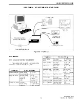
4. Connect the master transceiver to the slave (target)
transceiver by plugging the cloning cable into the
microphone jack of each.
5. Turn the slave transceiver on. Then momentarily
press the POWER switch of the master transceiver
to begin the data transfer.
6. When cloning is complete, CLONE is displayed by
the master and CLONE OK by the slave.
7. To clone another transceiver, repeat this procedure
starting with step 4.
8. To return both the transceivers to normal operation,
reconnect the microphone and cycle power.
.
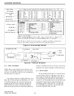
Figure 4-2 Memory Channel Screen (PMR Models)
Содержание 761X
Страница 9: ...GENERAL INFORMATION 1 4 November 1998 Part No 001 7600 001 This page intentionally left blank ...
Страница 11: ...GENERAL INFORMATION 1 6 November 1998 Part No 001 7600 001 NOTES ...
Страница 43: ...PROGRAMMING 4 18 November 1998 Part No 001 7600 001 This page intentionally left blank ...
Страница 87: ...UHF 7640 EXPLODED VIEW 7 22 November 1998 Part No 001 7600 001 FOLDOUT VHF Exploded View ...
Страница 89: ...VHF 7610 Transistor Basing Diagrams VHF 7610 Diode Basing Diagrams 8 2 November 1998 Part No 001 7600 001 ...
Страница 90: ...8 3 November 1998 Part No 001 7600 001 VHF 7610 MAIN BOARD BOTTOM VIEW FOLDOUT ...
Страница 91: ...8 4 November 1998 Part No 001 7600 001 VHF 7610 MAIN BOARD TOP VIEW ...
Страница 94: ...8 7 November 1998 Part No 001 7600 001 UHF 7640 MAIN BOARD BOTTOM VIEW FOLDOUT ...