


User Manual EE895
Miniature Sensor Module for CO
2
, Temperature and Barometric Pressure | 13
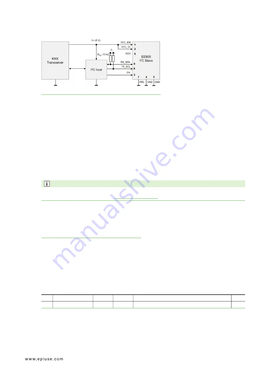
3.7.3. EE895 Connected to a KNX Bus
Fig. 11 Example KNX Bus
Pin 7 - ISEL is connected to the ground → the EE895 features I
2
C interface.
The VCC_EM and the VCC_IO are connected to the typical 5 V bus voltage.
The I
2
C host keeps the EE895 enabled with the pin 3 – EN and can read the values at any time, pin 6 - RDY is
not used.
4 Digital Interface
The EE895 features standard I
2
C and UART interfaces. The interface selection is made with pin 7 – ISEL, see
Tab. 2 Interface selection. On both interfaces, I
2
C and UART, the data is encapsulated in Modbus Protocol Data
Units (Modbus PDUs).
PLEASE NOTE
Modbus implementation details and request/response examples are described in detail in the Modbus
Application Note AN0103 (available at
4.1 I
2
C Interface
The EE895 supports the standard I
2
C specification. For detailed information about the I
2
C interface, please refer
to NXP document „I
2
C-bus specification and user manual“, Rev. 6, 4 April 2014:
https://www.nxp.com/docs/en/user-guide/UM10204.pdf
The I
2
C interface simultaneously supports two protocols on two different slave addresses:
▪
Modbus over I
2
C
address 0x5F
▪
I
2
C simplified
address 0x5E
These addresses are fixed, they cannot be changed by the user.
4.1.1. Modbus Protocol Over I
2
C Interface
I
2
C slave address: 0x5F
The I
2
C interface encapsulates the data according Modbus PDU packets, including CRC:
S
Slave Address
W
A
Request: Modbus PDU + Modbus CRC
P
S
Slave Address
R
A
Response: Modbus PDU + Modbus CRC
P
Every byte of the Modbus PDU and the Modbus CRC must be acknowledged (according to I
2
C specification, not
shown above).


