background image

Содержание FM-1

Страница 1: ...e men tioned in all communica tions concerning Dynakit PLEASE NOTE c If this f _ L tiler 10 chased t has b FMX_3 Din conjUnction ee pur te Ynath Wlth grator Jer MUlt 1 an t a few _ lp ex In nne Can b Iutes th F e saved b aSSembly e MX 3 insh referring t L uctlons Ii 0 rst Price 1 00 11629 ...

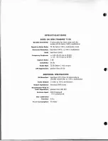
Страница 2: ... 20 cps to 20 KC 0 5 db 10 cps to 40 KC Capture Ratio 5 db Selectfvlty 54 db Audio Hum 73 db below 1 volt output AM Suppression greater than 63 db ADDITIONAL SPECIFICATIONS 1M Distortion less than 0 5 from 10 microvolts to 100 000 microvolts 100 modulation Audio Output 2 volts 100 modulation Output Impedance less than 5000 ohms Discriminator Peak to Peak Separation greater than 900 KC Antenna Inpu...

Страница 3: ...oduced a tuner which is unquestionably the lowest distortion receiver on the market today There are many parameters in addition to sensitivity and distortion which are part of a completely satisfactory tuner design Some are measurable some are intangible Extensive field testing under adverse and marginal con Aditions has proven the Dynatuner to be as fine a tuner as can be obtained today regardles...

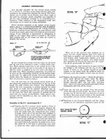
Страница 4: ...ring a portion of the alignment procedure the eye is connected to other specified parts of the circuit to indicate correct alignment This is the only instrument required during the alignment procedure The operating point of the eye has been set for extremely precise indication of the optimum tuning or alignment condition and is a more accurate indicator than tuning meters The action of the eye in ...

Страница 5: ...of the type which can be purchased for less than a dollar will g reatly facilitate cutting and stripping the various wires in t he kit A special alignment tool is provided with t he kit Good soldering technique is essential to satisfactory rCRults from any electronic equipment ALL SOLDERING MUST BE DONE WITH ROSIN CORE SOLDER There is no warranty on any equipment in which acid core solder has been...

Страница 6: ...mounted and solder splashes here will prevent a uniform contact You will note that on each etched circuit board all of the component positions are diagrammed on the top of the board the side without the copper The identification symbol for each component is marked between the holes into which its leads will be inserted Resistors may be identified by comparing them with the color code provided on t...

Страница 7: ...ed in the pictorial keeping it as short The leads of the disc capacitors may be bent slightly as pO isible and solder the lead to prevent them from falling out when the board i 7 turned over for soldering Be careful not to alloy 7V ount the spccifll temperature compensating capaci the lead to form a bridge to another portion of thl r 7 2 55 mmfd N2200 with six color stripes as circuit Solder each ...

Страница 8: ...nting holes in the board are not evenly spaced and the board can only be mounted in one position Fasten with eight sets of 4 j hardware 6 Mount the quadruple section electrolytic capaci tor C32 in the center of the chassis Note the 6 identifying marks at each lug of the capacitor semi circle square triangle and blank and orient the capacitor according to the pictorial diagram Fasten it rigidily in...

Страница 9: ...elet 17 on PC 8 8 Connect the other end to eyelet 14 8 16 J Connect one end of a 3 2 green wire to eyelet 1 on PC 7 8 Connect the other end to eyelet 5 8 17 Connect one end of a 7 green wire to eyelet 116 on PC 7 8 Connect the other end to eyelet 13 of PC 8 8 1M Connect one end of a 4 green wire to eyelet 19 on PC 8 8 Connect the other end to eyelet 1124 8 19 Connect one end of a 4 red wire to lug...

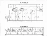
Страница 10: ... CIC 7 I 00 PC 7 CIRCUIT 09 1 2 C3 R2 R8 J i C2 C4 I CII 12 I V h U I 17 1 I R7 1 C6 0 1 I RS ITC I 1 0 I 1 __ I __ I S 7 2 pc a CIRCUIT A l t 41 I I I 31 _J RI2 31 _J RI4 fifi RIG 2 T 4 4 RI5 I I I I C20 I I II 31 L ___ J RI7 ...

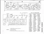
Страница 11: ...11 2 2 mmfd 432001 R13 10 000 ohms C 12 47 mmfd T 2 I F transformer 2 walt C 13 180 mmfd 432001 R 14 100 000 ohms C 14 0047 fd T 3 I F transformer R15 330000 ohms m 432001 R16 220 000 ohm C 15 47 mmfd NPO T 4 I F transformer s C 16 0047 mfd 432001 R17 62 000 ohms C17 47 mmfd NPQ T 5 Discriminator R18 100 000 ohms C 18 0047 mfd transformer R19 3 3 megohms C 19 0047 mfd 432002 R20 680 000 ohms C20 4...

Страница 12: ...o eyelet 113B on PC 8 This wire is connected on top of the board and soldered from ge1ow 15 Connect the free end of the red wire from the volume control to the top of eyelet 1136 on PC 8 i and solder it from below Eyelet 36 is located between the 100 000 ohm resistor brown black yellow and the mylar capacitor C29 Position the leads as shown in the pictorial and keep them clear of the board 16v Con...

Страница 13: ...er screw Cl D adjusts the mixer and the rear screw Cl B adjusts the RF stage The approximate settings given in steps 2 and 3 below have already been made as the capacitor is supplied to you 2 0Turn in the screw CloD on the center mixer I section until it is in all the way It should be snug but do not force it Then back it off i turn counter clockwise 30urn in the screw Cl B on the rear RF section ...

Страница 14: ... primary winding which is the next step At this point the tuning eye must be connected to another part of the circuit in order to measure the correct tuning point of the discriminator primary as set by the bottom slug If you are care ul it is possible to unsolder and resolder the required wires in this step and several succeeding steps without turning off the tuner However YOU MUST BE CONSCIOUS OF...

Страница 15: ...arent so it is essential that a weak signal be used here where the eye is about II open or proper alignment will not be realized To obtain a sufficiently weak signal it may be necessary to remove the antenna and substitute a short piece of wire Shorting out half the antenna is another alternative With signals of this magnitude a very few microvolts it will be noticed that the eye is sensitive to f...

Страница 16: ...pare the same system with phonograph or tape as a different program source to see if the effect can be localized to the tuner If it is definitely in the tuner it may be caused by improper discriminator 14 alignment and this portion of the alignment procedure should be repeated In the course of trouble shooting insped very carefully for bridges of solder from one point to another Also A recheck for...

Страница 17: ... any non standard parts used at net prices Parts which arc standard dealer items can be purchased from most elect ronic supply stores Shipment should be made by prepaid Railway Express where possible Returns will be made COD for freight and repair costs unless these have been prepaid If the PA 509 transformer is returned for factory repair or exchange it should be rcmoved from the tuner without cu...

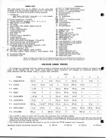
Страница 18: ...or dial disc l Y plastic insert for front plate brass front plate Part of similar type which do not change performance may sometimes be included as a matter of expediency This will account for slight variations in value and appearance VOLTAGE CHECK POINTS All voltages are measured with the volume control at minimum and the dial tuned between stations no signal sin many of the voltages will vary wi...

Страница 19: ......

Страница 20: ...5 ...

Отзывы: