


InsTallaTIon and feaTures
DYNATRON® T3™ HI-LO TREATMENT TABLE & T4™ TRACTION TABLE | OPERATOR’S MANUAL REV. 10 | 4/4/2018
4
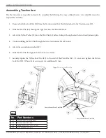
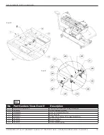
Assembling Traction Arm
The Traction Arm can quickly and easily be assembled by following the steps outlined below. An adjustable wrench is
required for assembly.
1. Remove the Nylon Lock Nut (30) from the Traction Arm Pivot Pin (28) attached to the Traction Arm (27).
2. Slide the Pivot Pin (28) through the upper traction arm Pivot Pin Hole.
3. Attach the Nylon Washer (29) onto the Pivot Pin (28) before sliding it through center hole in the adjustment plate.
4. Continue sliding the Pivot Pin through the lower traction arm Pivot Pin hole.
5. Attach the second nylon washer (29).
6. Slide the Pivot Pin through the hole in the Lower frame.
7. Securely tighten the Nylon Lock Nut (30) to the end of the Pivot Pin (28). Do not over tighten the Nylon
Lock Nut (30). When it feels secure, give it an additional ½ turn.
Upper Traction Arm Pivot Pin
RE
F
No. Part Numbers
27
Traction Arm Assembly (long)
28
Traction Arm Pivot Pin
29
Nylon Washer (.375 x .875 x .083)
30
3/8-16" Nylon Lock Nut
Lower Frame Pivot Pin Hole
Lower Frame Pivot Pin Hole


