11
CA500 O500EN1
INSTRUMENTS AND CONTROLS, FUNCTIONAL DESCRIPTION
13
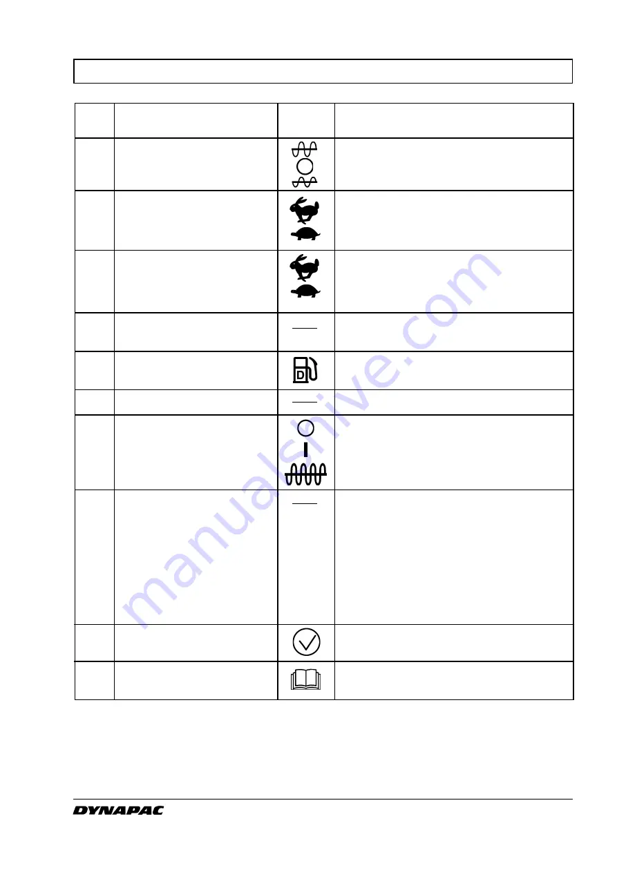
Amplitude selector
14
Speed selector, drum
15
Speed selector, rear axle
16
Revs control, diesel engine
17
Fuel gauge
18
Fuse box
19
Vibration ON/OFF, switch
20
Forward/Reverse control
21
Test button for warning lamps
22
Handbook compartment
Item in Designation
Symbol
Function
fig. 6
Left mode gives low amplitude.
Right mode gives high amplitude.
Vibration switched OFF in
O
mode.
Transport speed (High)
Working speed (Low)
Transport speed (High)
Working speed (Low)
Upper mode, engine working revs.
Lower mode, idling revs.
Indicates fuel level.
Contains fuses for the electrical system.
Push and release the switch to engage
vibration, push once more to disengage
vibration. The above applies only when the
amplitude selector (13) is in position High or
Low.
The lever must be in neutral to start the
engine, it cannot be started with the for-
ward/reverse lever in any other position.
Direction of travel and speed of the roller
is regulated with the forward/reverse lever.
The roller moves forward when the lever is
moved forward, etc. Speed of the roller is
regulated in proportion to how far the lever
is moved from neutral. The further from
neutral, the higher the speed.
The lamps 10, 11, 12 are checked when the
switch is pressed.
Stowage space for safety manual and
operator’s manuals.
Содержание CA500 Series
Страница 2: ...19 ILF015WO1...


