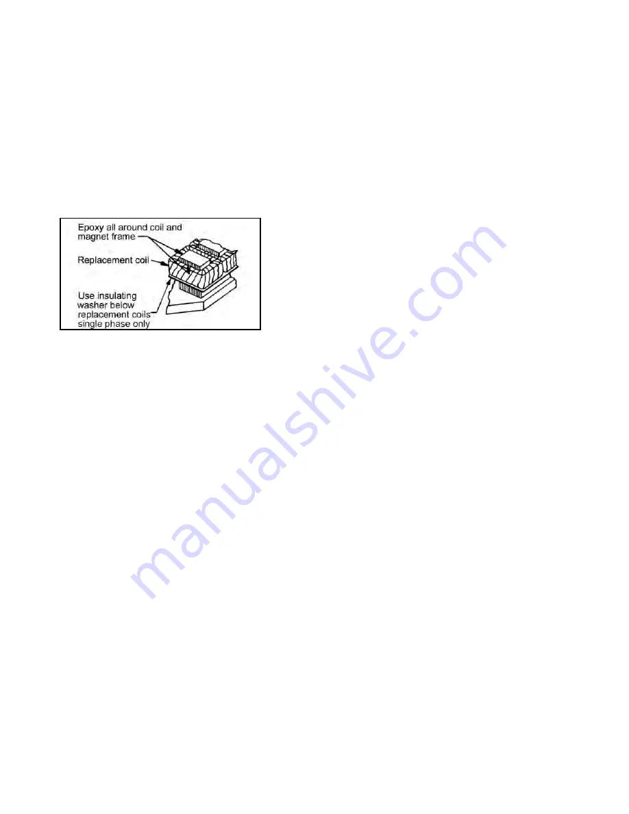
MAGNET COIL REPLACEMENT
(See Figures 1, 3 & 4)
Remove magnet assembly as outlined under FRICTION DISC
REPLACEMENT.
Coils (6b) are held in place with epoxy cement. Force coil off
magnet mounting plate and remove excess epoxy from all surfaces.
Replacement coils should be held in place with new epoxy cement.
The epoxy cement should be heat resistant and shock resistant.
Place an insulating washer (6c) below the coils. Order insulating wash-
ers when ordering coils. An insulating washer can be cut to
suit when replacing only one coil on a multiple coil assembly.
When installing coils, it is very important to follow EXACTLY the
sequence of black and light colored leads as shown in wiring
diagram (Figure 1). The brake will not operate properly unless coils
are all in the correct position.
Reassemble all parts in reverse order.
TROUBLE SHOOTING
A. IF BRAKE DOES NOT RELEASE:
1.
Check brake visually for broken or damaged parts.
2.
Check for broken leadwire or bad electrical connection.
3.
Check for correct voltage. Line voltage must correspond to
the voltage for which the brake coils are connected. If the
line voltage is more than 10% below the voltage for which
the brake coils are connected, the magnet will not pull in,
causing the coils to burn out within minutes. If the line voltage
is more than 10% above the voltage for which the brake coils
are connected, the coils will overheat and burn out.
4.
Check for burned-out coils (coils may be charred or burned).
5.
Check for excessive magnet gap. (See WEAR ADJUST
MENT.)
6.
Check for failure or power supply to brake.
B. IF BRAKE DOES NOT STOP:
1.
Check brake visually for broken or damaged parts.
2.
Make certain hub has not shifted position on the motor shaft
and that all rotating discs are fully engaged on the hub.
3.
Check that the manual release is in the normal position.
4.
Check disc wear. (See WEAR ADJUSTMENT.)
C. IF BRAKE CHATTERS OR HUMS:
1.
See that magnet faces are clean. To remove dirt, insert a
clean sheet of paper between magnet faces and energize
brake. Move paper around between faces to dislodge dirt,
then remove paper.
2.
Check for low voltage. Magnet will not pull in, and coils will
burn out if line voltage is beyond 10% below the voltage the
brake coils are connected for.
3.
See that magnet faces are parallel within tolerance.
Readjust magnet gap to “D” min.
(See WEAR ADJUSTMENT.)
4.
Check if shading coil (6d) is cracked, broken or out of
position (single phase only).
D. IF MANUAL RELEASE DOES NOT WORK:
1.
Check for broken or damaged parts.
2.
Check return spring (13). Brake will not reset automatically if
this spring is broken.
3.
Check quantity of shim washers (15) under release stop
screws. (See Manual Release Assembly under
“FRICTION DISC REPACEMENT”.)
Figure 3. Fastening of Replacement Magnet Coils
SPECIFICATIONS
MOTOR FRAMES -
182TC, 184TC, 213TC, 215TC, 254TC, 256TC.
ENCLOSURES
- NEMA 2
(material: aluminum and cast iron)
DUTY
- Rated for continuous duty.
VOLTAGES
- All standard NEMA voltages and frequencies available.
Other voltages and frequencies are optional.
MOUNTING
- Direct to NEMA “C” face, with one additional “C” face for
mounting of equipemnt to brake. Some standard motor shafts may
need modification, see Table 1.
Horizontal or vertical mounting with modifications.
ORDERING INFORMATION
The following data should be furnished with your order for:
REPLACEMENT PARTS
Brake Model Number
Part Number from Tables
Part Description from Tables
Hub Bore & Keyway. Shaft Extension Diameter & Keyway.
For electrical parts specify voltage, phase, and frequency.
REPLACEMENT BRAKE
Model Number
Voltage, Phase & Frequency
Hub Bore & Keyway Dimensions. Shaft Extension Diameter & Keyway.
Mounting - Horizontal or Vertical. (If vertical, specify whether above or
below motor.
3


