Dynamic CCTV DVR-8 Скачать руководство пользователя страница 9

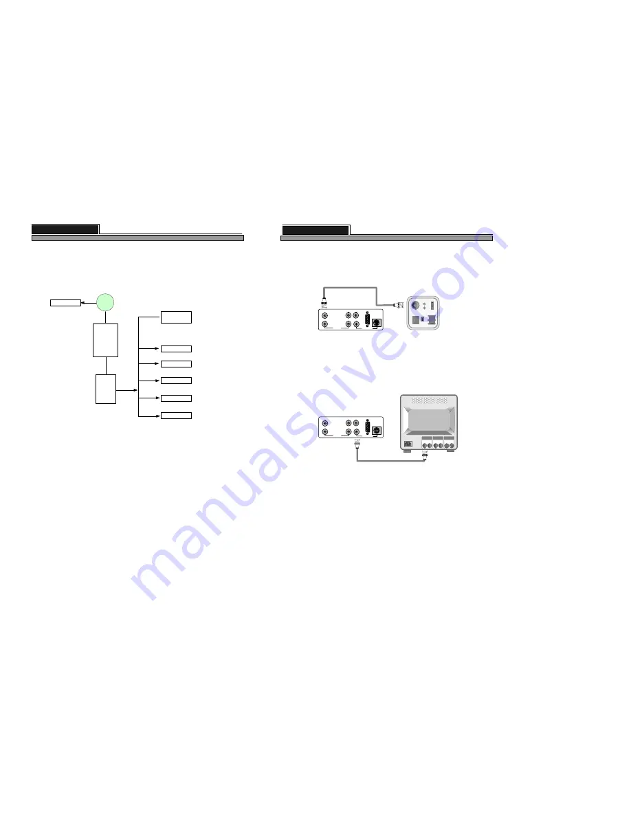
2-1. Camera Connection

Connect the camera to the CAMERA INPUT on the Rear Panel of the system.

2-2. Monitor Connection (Composite Connection Method)

Connect the monitor to the MONITOR OUT on the Rear Panel of the system

6

VIDEO

LENS

VIDEO

DC

AC24V/DC12

V.P

DC

LEVEL

Rear part of CAMERA

VIDEO A

IN

OUT

VIDEO C

IN

OUT

VIDEO B

IN

OUT

ALL ABOUT IMAGE RECOGNITION & PROCESSING

Notice : Connect camera or monitor to DVMR unit while DC power switch on the front panel is off.

                                     Setting video system : 

The DVMR set the video system of camera NTSC or  PAL automatically.

Screen positioning 

: If picture displayed in your monitor is not at the center of monitor, you can relocate

                                    images to make them shown in the middle of monitor.
                                    Press [P/T] button for a long time to enter into screen position mode, and you
                                    can adjust location of pictures using [UP], [DOWN], [LEFT] and [RIGHT]
                                    buttons. Press [P/T] button for a long time again to quit screen positioning mode.
                                    If you press [ENTER] button in the process of screen positioning mode, location
                                    of pictures return to original location set by manufacturer.

VCR

CH1

…...

CH8

MONITOR

LOOP

V
G
A

VCR

CH1

…...

CH8

MONITOR

LOOP

V
G
A

8 channel stand-alone DVMR

2. Installation

25

ALL ABOUT IMAGE RECOGNITION & PROCESSING

3) Example of Port Forwarding

Because ADSL is the most popular Internet service widely available in most of countries, we explain
more details about how to connect DVMR unit to ADSL line via Router or Gateway, to allow
accessing to this DVMR unit via Internet line far apart from DVMR unit.

Internet

PC

Client program

(remote viewer)

ADSL

modem

w/

dynamic IP

or

static IP

DVMR unit-1

Router

or

Gateway

PPPoE

protocol

Port Forwarding

(IP Forwarding)

DVMR unit-5

DVMR unit-4

DVMR unit-3

DVMR unit-2

Other

device(PC)

211.100.16.8

IP : 192.168.1.150
PORT : 8000

IP : 192.168.1.151
PORT : 8001

IP : 192.168.1.152
PORT : 8002

IP : 192.168.1.153
PORT : 8003

IP : 192.168.1.154
PORT : 8004

IP : 192.168.1.165
PORT : 8015

Intranet

Port forwarding : Port forwarding is called differently by each of router manufacturers, like IP forwarding,
IP bounding, port forwarding, port bounding or port routing. Our users can set port forwarding stated in
installation manual of router or gateway without big trouble, and complete IP network to which user can
connect many of our DVMRs, that are 1 ch DVMR, 4 ch DVMR, 8 ch DVMR and 16 ch DVMR, to access
to those units via Internet line far apart from those units.

Port forwarding is a kind of arrangement we have to set in web site of Router or Gateway to connect
external port to internal IP address, for example in above picture, PORT 8000 to IP 192.168.1.150,
PORT 8001 to IP 192.168.1.151, an so on.

According to our own test with NETGEAR Router, it is working perfectly, and we recommend our users
to adopt NETGEAR Router in case DVMR unit is connected to ADSL line.

PORT

           From  8000
           To  8015

8 channel stand-alone DVMR

3. Operation

Chapter 2.  Procedure

Содержание DVR-8

Страница 1: ...fore using the product STAND ALONE DVMR ALL ABOUT IMAGE RECOGNITION PROCESSING 8 Channel Digital Video Multiplex Recorder VER 2 0 ALL ABOUT IMAGE RECOGNITION PROCESSING 8 CH STAND ALONE DVMR The most...

Страница 2: ...ion point within an equilateral triangle is intended to alert the user to presence of important operating and maintenance Servicing instructions in the literature accompanying the appliance WARNING TO...

Страница 3: ...instructions on the first page of the text concerned with the installation of the device that these special accessories must be used with the device It is the responsibility of the user to use the ne...

Страница 4: ...R SYSTEM Log in 10 3 2 Recording 11 3 3 Playback 14 3 4 Set up 16 1 Basic operation 16 2 CAMERA SETUP 16 3 DISPLAY SETUP 17 4 TIME DATE SETUP 19 5 RECORD SETUP 19 6 HDD MANAGEMENT 21 7 MISCELLANEOUS S...

Страница 5: ...stable and meets our electricity requirements Unstable electricity will cause malfunction of the unit or give critical damage to the unit 6 Several chips on the main board of the DVMR unit and hard di...

Страница 6: ...TION PROCESSING OVERWRITE RECORD PLAY SETUP ZOOM MODE P T PIP FRZ SEQ PLAY MENU 1 2 3 4 8 channel stand alone DVMR Product package ALL ABOUT IMAGE RECOGNITION PROCESSING ALL ABOUT IMAGE RECOGNITION PR...

Страница 7: ...playback mode LEFT and RIGHT buttons are for selecting playback direction forward backward and UP and DOWN buttons are for increasing or decreasing speed of playback NOTICE If the Input window IR rece...

Страница 8: ...TITLE Default camera title is CH 01 CH 02 and so on 3 MOTION MASK Motion mask is for motion detection area motion window and sensitivity If we set MOTION MASK at YES all changes you made in MOTION SET...

Страница 9: ...es we explain more details about how to connect DVMR unit to ADSL line via Router or Gateway to allow accessing to this DVMR unit via Internet line far apart from DVMR unit Internet PC Client program...

Страница 10: ...ers must input manually or our DVMR can get those data automatically in case DVMR unit is connected directly to DHCP server in IP network To input each element of IP data move small triangular cursor...

Страница 11: ...To save settings and exit press MENU button BAUDRATE SETUP 2400 BPS CURRENT SPEED 4800 BPS 9600 BPS 9600 BPS 19200 BPS BAUDRATE SETUP SELECT THEN ENTER 1200 BPS CONFIRMATION VIA RS485 PORT on the bot...

Страница 12: ...ALARM SETUP In DVMR system 8 alarm input one for each channel and 1 alarm output relay out is provided and we can set type of alarm sensor independently in ALARM SETUP Or you can set all of input alar...

Страница 13: ...R BACK UP HDD MANAGEMENT SELECT PRESS ENTER 1 HDD CLEAR When DVMR system started to record and hard drive has data of pictures recorded IN USE is displayed in square brackets You are strongly requeste...

Страница 14: ...button POWER ON POWER OFF PAN LEFT PAN RIGHT TILT UP TILT DOWN P T LEFT UP P T RIGHT UP P T RIGHT DOWN P T LEFT DOWN ZOOM IN ZOOM OUT FOCUS FAR FOCUS NEAR FOCUS AUTO IRIS OPEN IRIS CLOSE IRIS AUTO AUT...

Страница 15: ...CH 03 CH 04 CH 05 CH 06 CH 07 CH 08 03 10 25 16 11 38 R 12 34 P 5 03 Indicates FRZ button is pressed 8 channel stand alone DVMR 3 Operation 19 ALL ABOUT IMAGE RECOGNITION PROCESSING 4 TIME DATE SETUP...

Страница 16: ...VITY is displayed press UP OR DOWN button to adjust sensitivity level from 1 to 10 In higher values it detect motion more sensitively If it is very low very slow movement is not detected even though m...

Страница 17: ...nu list of event shall be displayed Just select event from which you want to start playback using DOWN and UP buttons and then press PLAY button shortly to start playback If it is the right point from...

Страница 18: ...You can set at FACTORY DEFAULT all in one as a whole or group by group When cursor is at ALL SETUP you can set at ON or OFF by pressing ENTER button If you set ALL SETUP at ON all groups of settings a...

Отзывы: