Page 3
2282-TJ82 MANUAL - FORM 2282TJ-001
MODEL 2282-TJ82 DOUBLE/INSWING
ELECTROMAGNETIC LOCK
INSTALLATION INSTRUCTIONS
2/07
705 Emmett Street Bristol, CT 06010
1-877-DynaLock www.dynalock.com
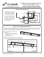
MOUNTING CONSIDERATIONS
Individual door and frame
conditions may vary. Dimensions
shown at right are for a typical
hollow metal door and frame.
The Lock Assembly should
be mounted in the center of
the frame. Verify that there
is proper clearance for the
lock assembly at the planned
mounting location.
1.
2.
INSTALL THE LOCK MOUNTING BRACKET
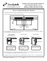
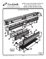
Separate the Lock Mounting Bracket from the Lock Assembly (see page 6). Standing at the “pull” side of the door,
place the Lock Mounting Bracket on the face of the frame header as shown below. Using the Template Drawing,
locate and mark the centers of the two slotted mounting holes and the wiring hole.
Drill the marked holes in the face of the
frame header:
a. two 1/8” holes for #10x1” sheet metal
screws or drill and tap for 10-24x1/2”
machine screws
b. one 5/8” hole for wiring
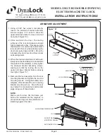
Attach the Lock Mounting Bracket to the frame header.
Tighten the screws just enough to allow for nal adjustment.
1.
2.
3.
SLOTTED MOUNTING HOLE
1/8”
ABOVE
HEADER
RABBET
WIRING HOLE
HINGE SIDE
OF DOOR
HINGE SIDE
OF DOOR
SLOTTED MOUNTING HOLE
BRACKET CENTERED ON FRAME

