Dynajet 200iP Скачать руководство пользователя страница 14

In Ground Model 200iP/250iP Motorcycle Dynamometer Installation Guide

C H A P T E R   1

Introduction


1-4

Y

OUR

 D

YNO

 R

OOM

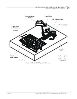
This section is not meant to imply that a dyno room is essential to repeatable results 
on a Dynojet dynamometer. However, a dyno room with an engine cooling intake fan, 
exhaust extraction, and noise reduction capabilities can add a new dimension to your 
shop.
A proper dyno room design will help to ensure repeatable, accurate runs. A good 
dyno room should do the following:
• minimize noise
• provide a controlled environment for testing
• provide a view window (safety glass) for customers
• be designed with safety in mind

Intake Air Fan—

After building your dyno room, you will need to supply an intake air 

fan. The intake air fan supplies air to cool the bike’s engine while supplying fresh 
oxygen for you and your bike to breathe. It is a common misconception that you 
cannot tune a bike without a large fan simulating exact road conditions; however, a 
good cooling fan is the only requirement for consistent diagnostics and tuning. The 
installed fan should be 5200 CFM.

Equalizer Box—

If the air flow rate coming into the dyno room is greater than the air 

flow rate leaving the dyno room, the room will become pressurized. A pressurized 
dyno room will make measured power misleading. To compensate, you need an 
equalizer box. The equalizer box is a baffled (to reduce noise) vent to the outside of 
your dyno room. The size of the equalizer box is dependent on the size of your dyno 
room and the size of your fans.

Exhaust Extraction—

An exhaust fan is needed to remove exhaust gasses, especially 

carbon monoxide, from the dyno room. Carbon monoxide is potentially lethal to 
people if not removed from the room and will affect engine power when mixed with 
fresh air. Plans for exhaust extraction (P/N 73429201) are available from Dynojet.

Engine exhaust contains poisonous carbon monoxide gas. Breathing it could 
cause death. Operate machine in well ventilated area.

Fire Suppression—

Always have adequate fire suppression or fire extinguishers in 

your dyno room.

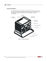
Industrial Noise Control, Inc.—

Industrial Noise Control, Inc. offers a zinc-coated 

steel room custom built to your specifications. This room meets all dyno room 
requirements. The dyno room must be clean and dry with a comfortable room air 
temperature above 32 degrees Fahrenheit (0 degrees Celsius), and have some system 
of exhaust extraction. For more information on a dyno room, refer to your 
Pre-Installation Guide For Model 200i, 250i, 200iP, and 250iP Motorcycle 
Dynamometers (P/N 98129103).

Содержание 200iP

Страница 1: ......

Страница 2: ...ppear in this manual Except as permitted by such license no part of this manual may be reproduced stored in a retrieval system or transmitted in any form or by any means electronic mechanical recording or otherwise without the prior written permission of Dynojet The Dynojet logo is a trademark of Dynojet Research Inc Any trademarks trade names service marks or service names owned or registered by ...

Страница 3: ...ents 1 5 Chassis Specifications 1 5 Compressed Air Requirements 1 8 Computer Specifications 1 8 Drill and Drill Bit Requirements 1 8 Electrical Requirements 1 8 Environmental Requirements 1 8 Forklift Requirements 1 8 Phone and Internet Access 1 9 Tie Down Straps 1 9 Dyno Electronics 1 10 Verify the Pit Dimensions 1 11 Chapter 2 Installation Dyno Drum Module Installation 2 2 Unpacking the Dyno 2 2...

Страница 4: ...urrent Brake Battery and Dyno Power Cables 2 38 Routing the Pickup Card and Dyno Electronics Cables 2 40 Routing the Air Pump Power Air Fuel Sensor and Dyno Electronics Power Cables 2 41 Wiring the Breakout Board 2 42 Power Carriage Installation 2 44 Tire Stop Installation 2 45 Final Adjustments and Tests 2 46 Turning On the Dyno Power 2 46 High Pressure Blower Test 2 47 Power Carriage Final Adjus...

Страница 5: ...p 4 9 Replacing the Theta Controller Fuses 4 10 Troubleshooting CPI Fuses 4 11 Chapter 5 Basic Dyno Operation Loading the Motorcycle 5 2 Connecting the RPM Pickup 5 5 RPM Pickup Descriptions 5 5 Connecting the Primary Inductive Pickup 5 6 Connecting the Secondary Inductive Pickup 5 8 Pre run Inspection 5 10 Before Starting the Engine 5 11 Engine Warm Up 5 11 After Engine Warm Up 5 11 Making a Test...

Страница 6: ...or Correct Voltages B 9 Replacing the Power Plug B 10 Hard Wiring to the Building B 10 Connecting the Dyno B 11 Appendix C EEC Finger Guard and Door Safety Switch Installation EEC Finger Guards C 2 Installing the EEC Finger Guards C 2 Adjusting the EEC Finger Guards C 3 Door Safety Switch C 4 Installing the Door Safety Switch C 4 Appendix D Theta Controller Power Adjustment D 2 Accessing the Dip S...

Страница 7: ...the dynamometer Dynojet is not responsible for damage incurred due to alteration of the dynamometer or components use of unapproved parts or abuse to the dynamometer Do not connect or disconnect cables or components on the dynamometer with the power on Always wear protective clothing ear protection and eye protection goggles safety glasses when using and servicing the dynamometer Equipment Power R...

Страница 8: ...ent to someone touch that person with your hand first then hand them the component Always carry circuit boards in anti static bags when the boards are exposed removed from the dynamometer Battery Fire and Explosion Hazards There is a danger of explosion if the battery is incorrectly replaced Replace only with the same or equivalent type recommended by the manufacturer Discard used batteries accord...

Страница 9: ...operate the dynamometer when there is excessive vibration or noise Resolve these problems before proceeding Never fuel the vehicle on the dynamometer unless appropriate safety measures are taken Verify brake operation before beginning any dynamometer testing Verify the vehicle is properly secured to the dynamometer Never operate the blowers without the guards installed Exercise care with any dynam...

Страница 10: ......

Страница 11: ...stic tools of WinPEP 7 software and a Dynojet dynamometer will give you the professional results you are looking for This document provides instructions for installing the in ground motorcycle dynamometer dyno This document will walk you through operating requirements installation accessories and basic dyno operation To ensure safety and accuracy in the procedures perform the procedures as they ar...

Страница 12: ...ES This chapter lists each dyno accessory alphabetically and describes the procedures for installing and using the accessory CONTROL PANEL INTERFACE OPERATION This chapter describes the Control Panel Interface CPI operating procedures BASIC DYNO OPERATION This chapter describes basic dyno operating procedures RED HEAD INSTALLATION This appendix describes the procedures for installing the Red Head ...

Страница 13: ...PLIANCE TESTING AND CERTIFICATION example of convention description The Caution icon indicates a potential hazard to the dynamometer equipment Follow all procedures exactly as they are described and use care when performing all procedures The Warning icon indicates potential harm to the person performing a procedure and or the dynamometer equipment RECORD The Record icon reminds you to record your...

Страница 14: ... rate leaving the dyno room the room will become pressurized A pressurized dyno room will make measured power misleading To compensate you need an equalizer box The equalizer box is a baffled to reduce noise vent to the outside of your dyno room The size of the equalizer box is dependent on the size of your dyno room and the size of your fans Exhaust Extraction An exhaust fan is needed to remove e...

Страница 15: ...ncluded with your dyno You will need to provide this battery For more information on installing the battery refer to Installing the Battery on page 2 30 CHASSIS SPECIFICATIONS description specifications Length with standard carriage allow 304 80 cm 120 00 in with extended carriage allow 355 60 cm 140 00 in pit covers 137 16 cm 54 00 in Height from bottom of dyno to top of dyno 45 72 46 67 cm 18 00...

Страница 16: ... E R 1 Dynamometer Specifications and Requirements 1 6 Figure 1 1 Model 250iP Dyno Dimensions PD153 standard carriage 304 80 cm 120 00 in extended carriage 355 60 cm 140 00 in 137 16 cm 54 00 in 45 72 46 67 cm 18 00 18 38 in 179 07 cm 70 50 in 76 20 cm 30 00 in 208 28 cm 82 00 in ...

Страница 17: ...0iP Motorcycle Dynamometer Installation Guide 1 7 Figure 1 2 Model 250iP Dyno with Accessories PD154 High Pressure Blower Eddy Current Brake Module Air Brake Option not shown Air Pump Option not shown Power Carriage not visible Monitor Support and Tray Dyno Module Control Panel Control Panel Interface houses all electronics not shown Wheel Clamp Option ...

Страница 18: ...a drill and drill bit capable of drilling holes in concrete Refer to Appendix A for more information on installing Red Head Anchors drill bit size 1 2 inch minimum hole depth 1 5 8 inch 41 2 mm ELECTRICAL REQUIREMENTS The Model 200iP 250iP dynamometers require a 240V 30a single phase electrical circuit for reliable and precise operation No other loads should be plugged into these circuits and thes...

Страница 19: ...ACCESS Dynojet recommends you have a phone close to the dyno to call for assistance in an emergency You may also wish to contact Dynojet to troubleshoot your dyno Internet access on your computer is desirable for contacting Dynojet and downloading new information and updates TIE DOWN STRAPS Dynojet recommends using motorcycle tie down straps for securing the bike on the dyno You will need to provi...

Страница 20: ...modules Atmospheric Sensing Module RPM Module Dynamometer Input Output Module and the CPU Module For more information refer to your WinPEP 7 User Guide P N 98128104 Figure 1 3 The Dyno Electronics 9 pin RS 232 socket CPU module atmospheric sensing module RPM module input output module 9 pin hand held pendant 3 pin power plug systemexpansion connector RPM inductive pickup socket 25 pin socket power...

Отзывы: