PSD 215 | 218
11
D
EVICE
S
ETUP
This dialog can be used for editing system parameters and
checking system properties. Some menu entries (e.g. Dis-
play Brightness) can be edited in the Device Settings
dialog after pressing the MENU/ENTER rotary encoder.
Other entries (e.g. Firmware Info) will open another dialog
when pressing the MENU/ENTER rotary encoder.
Display Brightness
The currently set display brightness (from 5% to 100%) is
indicated in the right column. Press the MENU/ENTER rota-
ry encoder to edit the value. Turn the MENU/ENTER rotary
encoder to the left to decrease the display brightness.
Turn the MENU/ENTER rotary encoder to the right to incre-
ase the display brightness. Press the MENU/ENTER rotary
encoder to apply the selected brightness. Pressing the
BACK function key returns to the menu.
Display Auto Dim.
The currently set time interval is shown. After the time in-
terval (from 10 seconds to 60 minutes) has expired the dis-
play backlight is dimmed. Press the MENU/ENTER rotary
encoder to edit the value. Turn the MENU/ENTER rotary
encoder to the left to shorten the time interval, or deac-
tivate the auto dim function by selecting Off. Turn the
MENU/ENTER rotary encoder to the right to extend the
time interval. Press the MENU/ENTER rotary encoder to
apply the selected setting. Pressing the BACK function key
returns to the menu.
Delay Unit
This parameter lets you select the unit of measurement
(Meter, Feet, Millisec or Samples) for the delay in the Sys-
tem Alignment dialog or DSP OUT Settings dialog. Press
the MENU/ENTER rotary encoder to edit the value. Turn
the MENU/ENTER rotary encoder to select the delay unit.
Press the MENU/ENTER rotary encoder to apply the se-
lected setting. Pressing the BACK function key returns to
the menu.
Lock Level
This parameter lets you select the the set of PSD parame-
ters to be locked after entering the PIN (see Lock Device
dialog). Table 2-14 lists the dialogs or parameters that will
be locked for the available lock levels.
HINT: The SUB Level parameter is never locked, so mut-
ing or adjusting the volume of the PSD is always
possible.
Factory Reset
The PSD can be reset to factory settings. Pressing the
MENU/ENTER rotary encoder opens a „Also clear User-
Mem?“ dialog box that lets the user choose between YES
or NO by turning the MENU/ENTER rotary encoder. Select
YES if all User Memories should be cleared. Select NO if
the User Memories should not be cleared. Pressing the
MENU/ENTER rotary encoder opens a safety dialog box
„Are you sure?“ that lets the user choose between YES or
NO by turning the MENU/ENTER rotary encoder. If YES has
been selected, pressing the MENU/ENTER rotary encoder
resets the PSD to its factory settings (see table 2-15) and
opens the Preset Select dialog. If NO has been selected, all
parameters stay unchanged and the display returns to the
menu. Pressing the BACK function key returns to the me-
nu.
Firmware Info
Press the MENU/ENTER rotary encoder to open the Firm-
ware Info dialog. This dialog shows the firmware versions
that are actually installed in the PSD. Pressing the BACK
function key returns to the menu.
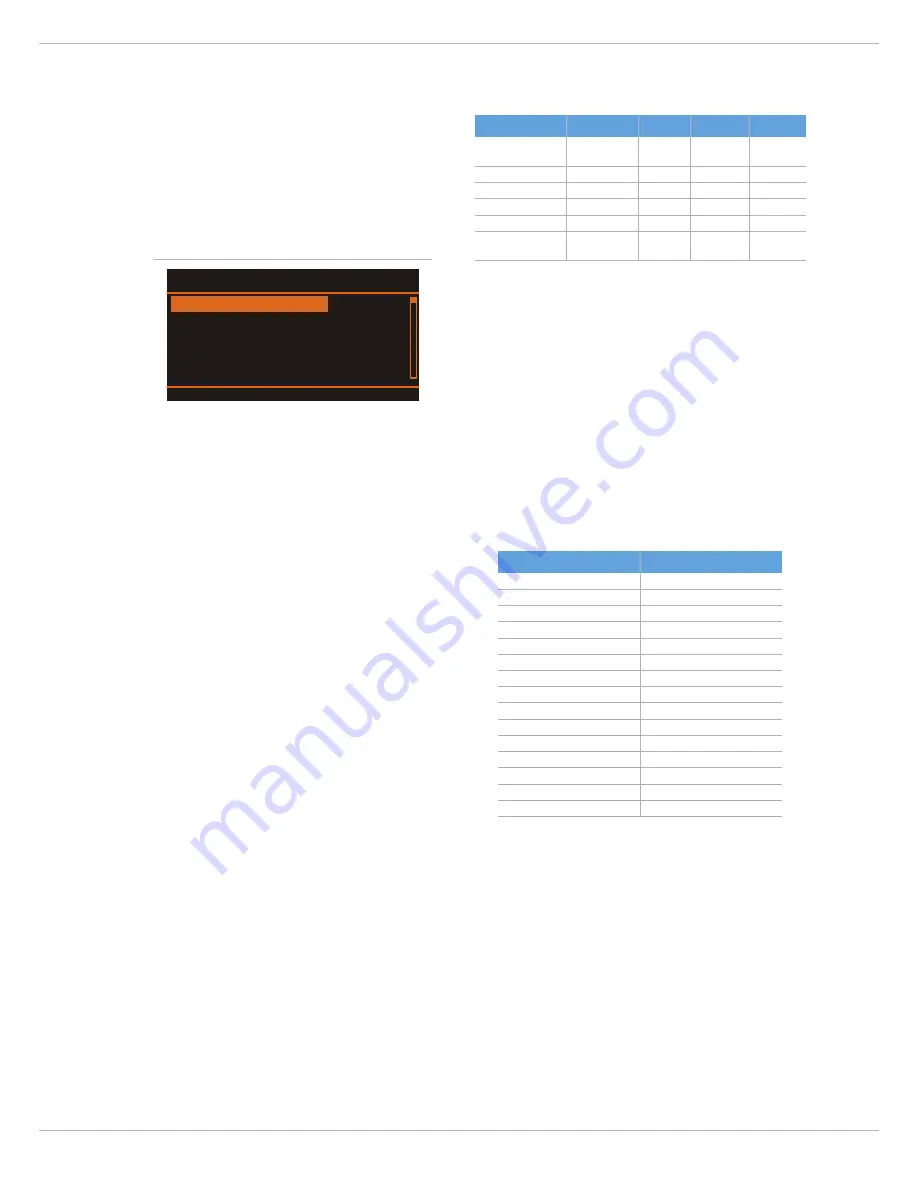
Illustration 2-13: Device Setup
Display Auto Dim. Off
Device Setup
Delay Unit Meter
Factory Reset ENTER
BACK
Display Brightness
100%
Dialog/Parameter
Control
1 Preset
2 System
3 DSPOut
Main Menu
MENU/ENTER
(press)
locked
locked
locked
Preset Select
PRESET
locked
locked
locked
System Equalizer
EQ
locked
locked
System Alignment
ALIGN
locked
locked
DSP OUT Settings
DSPOUT
locked
SUB Level
MENU/ENTER
(turn)
Table 2-14: Lock Level
Parameter
Value
SUB Level
0 dB
System Equalizer
flat (0dB)
SYS Level
0dB
SUB Delay
0.0cm
SUB Polarity
Normal
Generator
OFF
Testsignal
Pulse
DSP OUT Level
0dB
DSP OUT Delay
0.0m
DSP OUT Hi-Pass
Thru
DSP OUT Lo EQ
0dB
DSP OUT Hi EQ
0dB
Display Brightness
100%
Display Auto Dim.
Off
Delay Unit
Meter
Table 2-15: Factory Default Settings
Содержание PSD 215
Страница 1: ...PSD 215 218 POWERED SUBWOOFER Owner s Manual Bedienungsanleitung ...
Страница 2: ...PSD 215 218 2 ...
Страница 13: ...PSD 215 218 13 ...
Страница 25: ...PSD 215 218 25 3 1 Block Diagram Illustration 3 1 Frequency response of PSD 215 left and PSD 218 right ...
Страница 30: ...PSD 215 218 30 Notes ...
Страница 31: ...PSD 215 218 31 ...


