D 8A
6
4 L
IMIT
I
NDICATOR
(LIMIT)
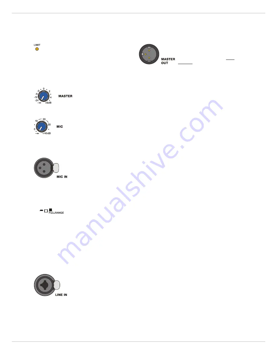
Brief blinking of the LIMIT LED indicates that the
power amplifier of the D 8A is operated at its limits.
Short-term blinking is uncritical, because the integ-
rated limiter compensates minor distortion. Constant ligh-
ting of the LED indicates that the sound is negatively
affected. Reducing the output volume is strongly recom-
mended.
5 M
ASTER
LEVEL
CONTROL
(MASTER)
Level control for adjusting the
power amp’s overall amplification.
6 M
ICROPHONE
LEVEL
CONTROL
(MIC)
Level control for adjusting the amp-
lification of the signal at the MIC IN in-
put.
7 I
NPUT
CONNECTOR
FOR
MICROPHONE
AUDIO
SIGNAL
(MIC IN)
Audio input for connecting an
balanced audio signal with micro-
phone level.
CAUTION:
Before making any connections or discon-
nections, make sure to set the level control
to the counterclockwise stop.
8 M
ODE
SELECTION
SWITCH
(LO-CUT/FULLRANGE)
If the D 8A is used as a fullrange sys-
tem, select FULLRANGE (button not
pressed).
If a subwoofer without a low-cut signal output is used, i.e.
the identical audio signal is used for the D 8A and the
subwoofer, select LO-CUT (button pressed) for activating
the internal low-cut filter of the D 8A. If the D 8A is con-
nected to the HI OUT output of a subwoofer with integ-
rated low-cut filter, select FULLRANGE to avoid having the
two low-cut filters of the subwoofer and D 8A in series.
The setting LO-CUT can also be used for monitor or delay
applications, when a high bass level is not necessary.
9 I
NPUT
CONNECTOR
FOR
AUDIO
SIGNAL
(LINE IN)
Electronically balanced input for the
connection of a line level signal sour-
ce such as mixer, signal processor,
etc. Establishing a connection is pos-
sible via phone or XLR-type plugs.
Whenever possible, balanced signal
feed is always preferable to guard against potential noise
or HF-interference.
CAUTION:
Before making any connections or discon-
nections, make sure to set the level control
to the counterclockwise stop.
10 O
UTPUT
CONNECTOR
(MASTER OUT)
The output connector provides the
Master Signal (Line+Mic) for ”carry-
ing through“ the input signal. The
level of the output signal is inde-
pendent of the setting of the Mas-
ter level control (”Pre Fader”).
2.2 Cooling
This is a powered speaker with a very high efficient amp-
lifier module and as a result does not get really hot. The
temperature of the amplifier module is monitored. In the
rare event it does get too hot it will automatically shut
down to protect itself. Once its temperature has returned
to within its operating range the amp will turn back on.
This may happen when the speaker is operated in very high
ambient temperatures and the enclosure is exposed to di-
rect sunlight. Always ensure adequate cooling and appro-
priate shade to keep the ambient temperature around the
product within the specified operating temperature range.
2.3 System Setup
CAUTION:
After installing the system, first switch on
the mixing console and position the mixer’s
master faders to their minimum settings.
That followed, switch on the D 8A and use
the MASTER to adjust the desired volume
setting. Otherwise, high sound levels
caused by unintentional playback of a pro-
gram source could be the result, which
might cause hearing damage.
This Quick Start Manual outlines setup and operation of
the D 8A connected to a DYNACORD CMS mixer.
1.
Place the D 8A, mounted on pole-mount stands to
the left and to the right. The lower edges of the
speaker systems should be approximately 1,8 meters
above the audience to provide sufficient coverage
and to prevent that listeners nearby are subject to
extreme sound levels.
2.
Using suitable XLR-type cables connect the Master
Outputs of your mixing console, e.g. DYNACORD
CMS 1000, to LINE IN of the D 8A. Position the mas-
ter faders on the mixer to their minimum setting.
Now, switch on the mixer.
3.
Connect the D 8A to the mains outlet using the sup-
plied mains cord. Plug the connector into the MAINS
IN socket. Use the Mains switch to power-up the
D 8A.
4.
Set the level control MASTER of the D 8A to 0dB.
5.
Connect a audio source, e.g. CD player, to a line level
input of the mixer, e.g. CMS 1000. Set all rotary
controls of the mixing console input channel to their
center position. Adjust the input channel’s ‘Gain‘
control so that the Peak LED should not light at all or
blink only once in a while.
6.
Slowly raise channel fader and master faders on the
mixing console to the desired positions – i.e. volume
settings.
LO-CUT
Содержание D 8A
Страница 1: ...D 8A ACTIVE FULLRANGE CABINET Owner s Manual Bedienungsanleitung Mode d emploi ...
Страница 8: ...D 8A 8 ...
Страница 14: ...D 8A 14 ...
Страница 21: ...D 8A 21 3 1 Block Diagram 3 2 Frequency Response 3 3 Beamwidth Lo Cut ...
Страница 22: ...D 8A 22 3 4 Directivity HORIZONTAL DIRECTIVITY VERTICAL DIRECTIVITY ...
Страница 23: ...D 8A 23 3 5 Dimensions 3 6 Setup Example ...


