Diamond Impregnated Steel Wheel Mounting
• With power source disconnected from the air tool, mount recommended accessory into collet assembly.
• The mandrel diameter of the abrasive/accessory must insert freely, but not loosely, all the way to the base
of the collet body before tightening the collet cap. Use wrenches provided.
Caution:
The mandrel shall be inserted to the full depth of the gripping jaws of the collet.
At least 13mm of the mandrel length shall be inserted into the collet to prevent excessive overhang.
DO NOT extend the mounted wheel below the shroud base plate. Refer to accessory manufacturer's
instructions for proper overhang.
Warning:
Sliding the accessory’s mandrel out from the collet insert creates an “OVER HANG” condition.
This practice is NOT recommended, reducing the free speed of the tool by reducing the air pressure
must be done to avoid cutting tool breakage and serious injury. Improper mounting of an accessory may
cause excessive vibration levels or damage to the accessory.
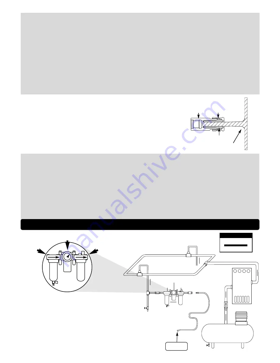
To Tool Station
Closed Loop Pipe System
(Sloped in the direction of air flow)
Ball
Valve
Ball
Valve
Filter
Regulator
Lubricator
Air Flow
Drain
Valve
Drain
Valve
Air Compressor
and Receiver
Drain Valve
Air Hose
Air Flow
Refrigerated
Air Dryer
2
Filter
Regulator
Lubricator
90 PSIG
(6.2 Bar)
SAFETY INSTRUCTIONS CONT.
• Follow tool specifications before choosing size and type of accessory.
• Only use recommended fittings and air line sizes. Air supply hoses and air hose accessories must have a minimum working pressure of 150 PSIG (10 Bars, g) or 150 percent of the maximum
pressure produced in the system, whichever is higher. (See tool Machine Specifications table.)
OPERATING INSTRUCTIONS
Warning:
Always wear personal protective equipment. Operator of tool is responsible for following: accepted eye, face, respiratory, hearing and body protection.
Warning:
Always use wheel shroud. Make sure it is positioned to best protect the operator and make sure it is securely fastened. Wheel shrouds that are worn, damaged or have been subject to a
wheel breaking must be replaced
.
Caution:
Hand, wrist and arm injury may result from repetitive work, motion and overexposure to vibration.
• Keep hand and clothing away from working end of the air tool, working end of air tool has the potential of cutting and severing.
• Keep slot width constant or increased.
• DO NOT side grind with cut-off wheels.
• If wheels get jammed in cut slot, shut off the cut-off tool, ease wheel from slot. Check that the wheel is still correctly secured and not damaged before continuing the operation.
• Note the tool run down time. Control the tool as if the tool were under power.
• Release the throttle lever in case of an interruption of the energy supply.
Operation: Be sure that any loose clothing, hair and all jewelry is properly restrained.
• Secure inlet bushing on air tool with a wrench before attempting to install the air fitting to avoid damaging housing assembly.
• BEFORE MOUNTING A WHEEL, after all tool repairs and whenever a cut-off tool is issued for use, check tool RPM (speed) with tachometer with air pressure set at 90 PSIG while the tool is
running. If tool is operating at a higher speed than the RPM marked on the tool housing, or operating improperly, the tool must be serviced and corrected before use.
Caution:
Tool RPM must never exceed abrasive/accessory RPM rating. Check accessory manufacturer for details on maximum operating speed or special mounting instructions.
• Connect air tool to power source. Be careful NOT to depress throttle lever in the process.
Do not expose air tool to inlet pressure above 90 PSIG or (6.2 Bars).
Caution:
After installing the accessory, make sure that no one is in the unguarded plane of the wheel before starting the cut-off tool. IN A PROTECTED AREA, test run the wheel at a reduced speed to
check for good balance. Gradually increase tool speed. DO NOT USE if tool vibration is excessive. Correct cause, and retest to insure safe operation. Test wheel at its free speed (RPM) in a
protected area for at least one minute before applying the wheel to the work.
• DO NOT let the airline impede operating motion.
• Make sure that work area is uncluttered, and visitors are at a safe range from the tools and debris.
• Air tools are not intended for use in explosive atmospheres and are not insulated for contact with electric power sources.
• Use a vise or clamping device to hold work piece firmly in place.
• Do not apply excessive force on tool or apply “rough” treatment to it.
• Always work with a firm footing, posture and proper lighting.
• Ensure that sparks and debris resulting from work does not create a hazard.
• This tool has rear exhaust. Exhaust may contain lubricants, vane material, bearing grease, and other materials flushed thru the tool.
Warning:
Cutting certain materials can create explosive dust. It is the employers responsibility to notify the user of acceptable dust levels.
• Cutting can cause sparks which can cause fires or explosions. It is the users responsibility to make sure the work area is free of flammable materials.
Report to your supervisor any condition of the tool, accessories, or operation you consider unsafe.
Air System
1
DROP/MIN.
20
SCFM
LUBRICATOR SETTING
•
Dynabrade Air Power Tools are designed to
operate at 90 PSIG (6.2 Bar/620 kPa) maximum
air pressure at the tool inlet, when the tool is
running. Use recommended regulator to control
air pressure.
•
Ideally the air supply should be free of moisture.
To facilitate removing moisture from air supply, the
installation of a refrigerated air dryer after the
compressor and the use of drain valves at each
tool station is recommended.
➤
➤
➤
➤
➤
➤
90 PSIG MAX
(6.2 Bar)
Air Tool
Correctly Mounted Side View
Collet Cap
Collet Body
Collet Insert
Diamond Impregnated Steel Mounted Wheel


