5
Disassembly/Assembly Instructions
Important: Manufacturer’s warranty is void if tool is disassembled before warranty expires
Notice: Dynabrade strongly recommends the use of their 52296 Repair Collar (sold separately) during assembly/disassembly activities. Failure to
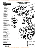
use this collar will highly increase the risk of damage to the valve body of this tool. Please refer to parts breakdown for part identification.
To Disassemble:
1.
Disconnect tool from power source.
2.
Secure air tool in vise using
52296
Repair Collar.
3.
Remove
51344
Back-Up Pad. Take off
52742
Shroud by unscrewing
97326
Clamp.
4.
With an adjustable pin wrench or
50971
Lock Ring Tool, remove
01560
Exhaust Cover by turning counter-clockwise.
5.
Pull motor assembly from housing.
6.
Reposition motor housing in vise so inlet bushing is facing upwards.
7.
Remove
94523
Inlet Bushing and muffler assembly from valve body housing. Using needle nose pliers, remove spring, tip valve and seal.
8.
Remove
95711
Retaining Ring from inlet adapter and disassemble muffler assembly.
9.
Using a 2.5mm diameter drift pin and a hammer, tap
12132
Pin out from housing and remove throttle lever.
10.
Remove
95558
Retaining Ring and push
01469
Speed Regulator from housing.
Motor Disassembly:
1.
Remove
50133
Adapter from rotor shaft by inserting 3mm hex wrench through adapter and into rotor shaft. Twist adapter from shaft.
2.
Remove
01478
Front Bearing Plate, cylinder, blades (4) and
01479
Spacer from rotor.
Note: 02649
Bearing is a slip fit into
01478
Front Bearing Plate.
3.
Press rotor from
02673
Rear Bearing Plate. Press
02696
Bearing from rear bearing plate. (
96210
Bearing Removal Press Tool is available.)
Motor Disassembly Complete.
Motor Assembly
:
Important:
Be sure parts are clean and in good repair before assembling.
1.
Place
01594
Rotor in padded vise with threaded spindle facing upwards.
2.
Slip
01479
Spacer onto rotor.
3.
Place a .002" shim into
01478
Front Bearing Plate as an initial spacing (
Note: 54529
Shim Pack contains .001" and .002" shims) and slip
02649
Bearing into plate.
4.
Install bearing/bearing plate assembly onto rotor.
5.
Tighten
50133
Adapter onto rotor (torque to 17 N•m/150 in. - lbs.).
6.
Check clearance between rotor and bearing plate by using a .001" feeler gauge. Clearance should be at .001" to .0015". Adjust clearance by repeating
steps 1-5 with different shim if necessary.
7.
Once proper rotor/gap clearance is achieved, install well lubricated
01480
Blades (4) into rotor slots. Dynabrade Air Lube P/N
95842
is
recommended for lubrication.
8.
Install cylinder over rotor. Be sure air inlet holes of cylinder face away from front bearing plate and that the pin in the front bearing plate aligns correctly
with the pin-hole in the cylinder.
9.
Press against outer race of
02696
Rear Bearing and install into
02673
Rear Bearing Plate (
96242
Bearing Press Tool available). Press bearing/bearing
plate assembly onto rotor. Be sure that pin and air inlet holes line-up with pin slot and air inlet holes in cylinder.
Important:
Fit must be snug between bearing plates and cylinder. A loose fit will not achieve the proper preload of motor bearings. If too tight, rotor will
not turn freely. Rotor must then be lightly tapped at press fit end so it will turn freely while stillmaintaining a snug fit.
10.
Secure motor housing in vise using
52296
Repair Collar with motor cavity facing upwards.
11.
Install motor assembly into housing. Be sure motor drops all the way into housing.
12.
Insert
01580
Silencer into
01560
Exhaust Cover and install onto motor housing. Apply #567 Loctite (or equivalent) to housing threads.
Torque to 28 N•m/250 in. - lbs.
13.
Motor adjustment must now be checked. With motor housing still mounted in vise, pull end of rotor and twist (10-15 lbs. force), rotor should
turn freely without drag. If drag or rub is felt, then increase preload or remove shim. Also, push end of rotor and twist (10-15 lbs. force), rotor
should turn freely without drag. If drag or rub is felt, then deload or add shim.
14.
Place
52742
Shroud onto housing and fasten
97326
Clamp.
15.
Install
51344
Pad and abrasive.
Motor Assembly Complete.
Buy parts on line at https://Dynashop.co.uk/ for all things Dynabrade
Buy parts on line at https://Dynashop.co.uk/ for all things Dynabrade


