background image


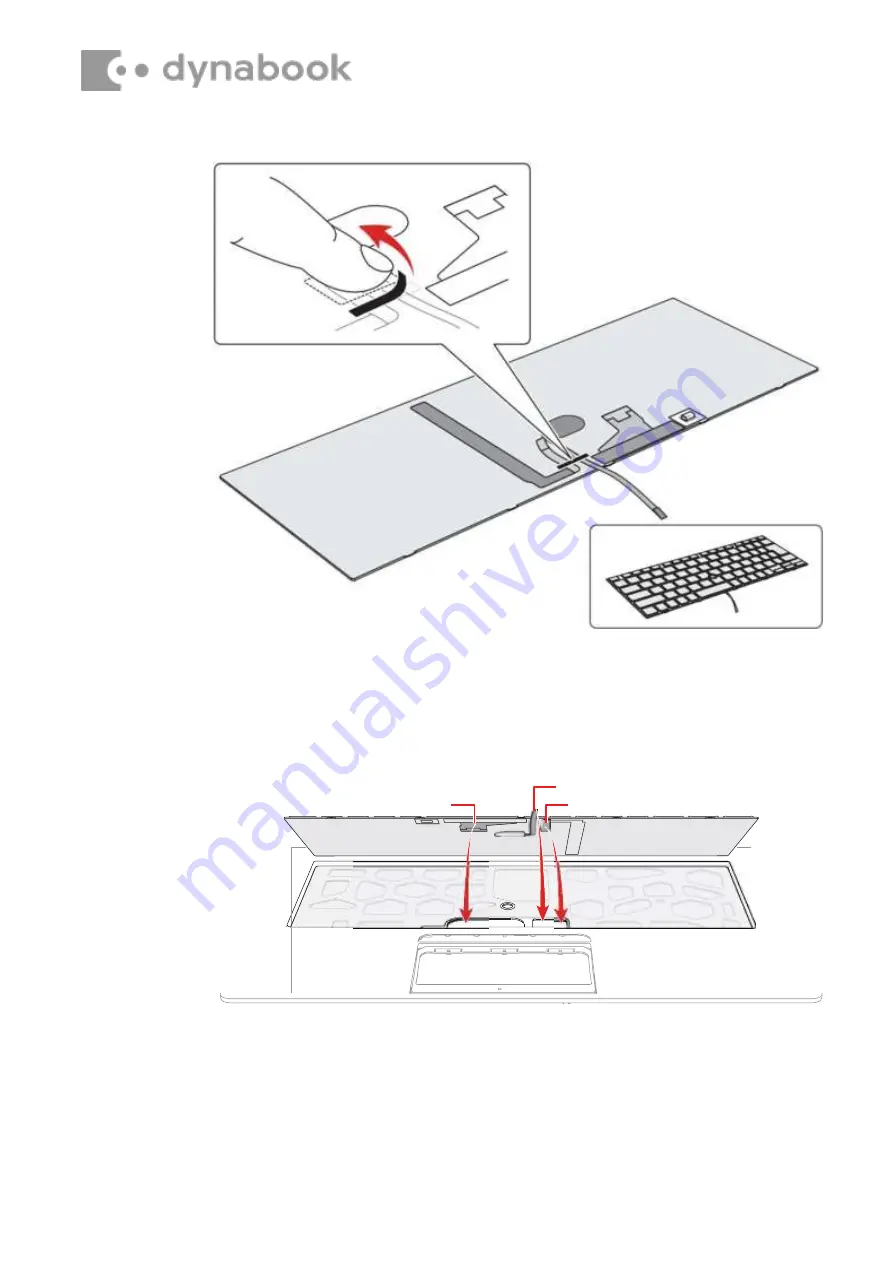
Keyboard  FPC


Accu Point FFC


Keyboard Backlight harness


Figure 4-45 Installing the keyboard (4)


5.  Set the 

Keyboard FPC, 

the 

Keyboard Backlight harness 

and the 

Accu Point FFC 

to the slot. Extra portion of the 

Keyboard FPC, 

the 

Keyboard Backlight harness 

and the 

Accu Point FFC 

must be put 

under the Cover Assembly. 

Figure 4-46 Installing the  keyboard (5)


6.  Stick the new keyboard to the Cover Assembly, the bottom side of the 

keyboard first. Make sure the right & left side gaps are equal and the 
corners are sticked in place. 

Содержание PORTEGE X40-G

Страница 1: ...waste electrical and electronic equipment WEEE All of the instructions provided within this letter can be reviewed in greater detail within the Portege X40 G Series Maintenance Manual Tools Required...

Страница 2: ...fication and removal of the lithium ion battery Further maintenance instructions can be found in section 4 5 of the Portege X40 G Maintenance Manual Some tools are required in order to remove this com...

Страница 3: ...nd refer to Figure 4 6 1 Disconnect the BATTERY HARNESS from the connector CN8021 on the SYSTEM board 2 Remove the following screws and the battery pack Base assembly Cover Assembly Latch Take care no...

Страница 4: ...he Portege X40 G Series Maintenance Manual to check how the mainboard is removed Please refer to the information below for the removal of the SSD One Philips screwdriver with type 1 bit will be requir...

Страница 5: ...1 Remove the following screw and disconnect the SSD from the connector CN1910 on the SYSTEM board Figure 4 32 Removing the SSD SSD CN1910 S2x3BT...

Страница 6: ...Beside the LCD and the main PCB there are further small PCBs and components which are in the scope of the WEEE Directive The removal of these components is described in detail in the chapter 4 of the...

Страница 7: ......

Страница 8: ...teps below and refer to Figure 4 4 to Figure 4 5 1 Close the display panel and turn the computer face down 2 Remove the BOTTOM CUSHION M on the center of the Base Assembly 3 Remove the following screw...

Страница 9: ...install the Base Assembly follow the steps below and refer to Figure 4 4 to Figure 4 5 1 Set the Cover Assembly on the Base Assembly while securing the latch 2 Secure the Cover Assembly and Base Assem...

Страница 10: ...tteries approved by Dynabook Check the battery s terminals visually If they are dirty wipe them cleanwith a dry cloth Figure 4 6 Releasing the battery pack 4 12 2 Installing the Battery pack To instal...

Страница 11: ...steps as detailed below 1 Align the notch of the memory module with that of the memory slot and gently insert the module into the slot at about a 30 degree angle before holding it down until the latc...

Страница 12: ...d slot 4 14 1 Removing the Smart Card slot To remove the Smart Card slot unit follow the steps below and refer to Figure 4 9 to Figure 4 10 1 Disconnect the Smart Card slot FFC from the connector CN21...

Страница 13: ...Removing the Smart Card slot 2 4 14 2 Installing the Smart Card slot To install the Smart Card slot follow the steps below and refer to Figure 4 9 to Figure 4 10 1 Connect the Smart Card slot FFC to...

Страница 14: ...and remove the board Figure 4 11 Removing the LED board 3 Disconnect the LED board FUR3LE FFC from the connector CN9571 on the LED board FUR3LE 4 15 2 Installing the LED board FUR3LE To install the L...

Страница 15: ...nd refer to Figure 4 12 to Figure 4 16 1 Disconnect the Click Pad FFC and Fingerprint FFC from the connector on the Click Pad and the connector CN9560 and CN9550 on the System Board Figure 4 12 Removi...

Страница 16: ...4 Disconnect the Speaker harness from the connector CN6000 on the system board 5 Open the INSU and stick tape Release the Speaker harness from the guides Figure 4 15 Removing the Speaker 4 6 Remove th...

Страница 17: ...the screws 2 Arrange the Speaker harness under the guides as shown below and fix it with the new INSU 3 Connect the Speaker harness to the connector CN6000 on the system board 4 Arrange the rest of Sp...

Страница 18: ...al button unit To remove the dual button unit follow the steps below and refer to Figure 4 18 to Figure 4 20 1 Remove the following screws and then remove the dual button plat Figure 4 18 Removing the...

Страница 19: ...the Dual button FPC to the dual button plat and secure it with the screws 3 Set the Dual button plat to the Cover Assembly and secure it with the screws 4 18 3G module USB board 4 18 1 Removing the 3...

Страница 20: ...dule 1 3 Remove the following screw and disconnect the 3G MODULE from the connector CN2610 on the USB board FUR3CN Figure 4 22 Removing the 3G module 2 4 Disconnect the FPC FMR3YC from the connector C...

Страница 21: ...N follow the steps below and refer to Figure 4 21 to Figure 4 24 1 Set the USB board FUR3CN to the Cover Assembly and secure it with the screws 2 Connect the FPC FMR3YC to the connector CN9510 on the...

Страница 22: ...2 3 Release the Wireless LAN antenna cable from the guides on the Fan 4 Remove the screw securing the Wireless LAN card 5 Disconnect the Wireless LAN card from the connector CN2630 on the System Board...

Страница 23: ...card Figure 4 26 Arranging Wireless LAN antenna cable 5 Stick a new INSU WL in place 4 20 Fan 4 20 1 Removing the Fan To remove the Fan follow the steps below and refer to Figure 4 27 1 Disconnect th...

Страница 24: ...ow and refer to Figure 4 27 1 Set the Fan in place on the Cover Assembly and secure it with the screws 2 Connect the Fan harness to the connector CN3380 on the System Board FUR3SY 4 21 Fin 4 21 1 Remo...

Страница 25: ...lso update with the latest BIOS and EC KBC as described in Appendix G BIOS Rewrite Procedures and Appendix H EC KBC Rewrite Procedures When replacing the system board with a new one the ProductKey MBR...

Страница 26: ...Keyboard Backlight harness from the connector CN3270 on the System Board FUR3SY When replacing the system board with a new one stick a new INSU BOSS on one side of the system board in place When repl...

Страница 27: ...nnect the camera harness from the connector CN9540 on system board 4 Disconnect the LCD harness from the connector CN5930 on the System Board FUR3SY Figure 4 30 Removing the system board 2 5 Remove th...

Страница 28: ...with the screws 3 Connect the LCD harness to the connector CN5930 on the System Board FUR3SY 4 Connect the camera harness to the connector CN9540 on system board 5 Connect the Keyboard Backlight harn...

Страница 29: ...he following screw and disconnect the SSD from the connector CN1910 on the SYSTEM board Figure 4 32 Removing the SSD 4 23 2 Installing the SSD To install the SSD follow the steps below and refer to Fi...

Страница 30: ...igure 4 34 1 Release the latch from the slot on the Cover Assembly 2 Remove the Power button from the Cover Assembly Figure 4 34 Removing the Power button 4 24 2 Installing the Power button To install...

Страница 31: ...e Click pad To remove the Click pad follow the steps below and refer to Figure 4 36 to Figure 4 37 1 Peel off the Click pad from the Cover Assembly Figure 4 36 Removing the Click pad 1 2 Remove the fo...

Страница 32: ...the Click pad To install the Click pad follow the steps below 1 Insert a new Click Pad Plate to the right hole on the Cover Assembly Figure 4 38 Installing the Click pad 1 2 Align the left hole on the...

Страница 33: ...follow the order on Figure 4 37 4 Peel off the separator on the new Click Pad Plate and stick a new Click pad to the Cover Assembly Figure 4 40 Installing the Click pad 3 4 26 Keyboard 4 26 1 Removing...

Страница 34: ...to Figure 4 48 1 Remove the used INSU KB on the Cover Assembly and stick a new INSU KB in place Figure 4 42 Installing the keyboard 1 2 Make sure the whole INSU KB is flatly sticked including the fou...

Страница 35: ...Figure 4 43 Installing the keyboard 2 3 Peel off the separator from the lower center Figure 4 44 Installing the keyboard 3 4 Peel off the stick tape on the back of a new keyboard...

Страница 36: ...ccu Point FFC to the slot Extra portion of the Keyboard FPC the Keyboard Backlight harness and the Accu Point FFC must be put under the Cover Assembly Figure 4 46 Installing the keyboard 5 6 Stick the...

Страница 37: ...Figure 4 47 Installing the keyboard 6 7 Press the four sides of the KB according to the directions in the following figure to ensure the installation Figure 4 48 Installing the keyboard 7...

Страница 38: ...fer to Figure 4 49 to Figure 4 53 1 Release the following screws and separate the LCD Assembly and Cover Assembly Figure 4 49 Removing the LCD unit 1 2 Remove both hinge caps When replacing the COVER...

Страница 39: ...emoving the LCD unit 2 3 Release the following screws and remove the left right hinges Figure 4 51 Removing the LCD unit 3 4 Release the latches and remove the LCD mask Be sure to release the latches...

Страница 40: ...utter Figure 4 52 Removing the LCD unit 4 5 Peel off the insulators securing the LCD harness and release the release the LCD harness 6 Take out the LCD unit Be careful that the LCD harness is connecte...

Страница 41: ...the LCD unit 5 4 27 2 Installing the LCD unit To install the LCD unit follow the steps below 1 Connect the LCD harness to the connector on the LCD unit and secure it with the pull tape and glass tape...

Страница 42: ...Figure 4 54 Installing the LCD unit 1 5 Peel off the separators on the bottom of the LCD mask and set the LCD mask on the LCD cover while engaging the latches...

Страница 43: ...32 33 33 2 4 8 10 12 3 5 6 7 9 11 13 Be sure to engaging the latches follow the order on below figure When setting the LCD mask be careful not to pinch the cables Figure 4 45 Installing the LCD unit 2...

Страница 44: ...y and secure them with the screws 4 28 Camera module Wireless antennas 4 28 1 Removing the Camera module To remove the camera module follow the steps below and refer to Figure 4 57 to Figure 4 60 1 Pe...

Страница 45: ...module Figure 4 58 Removing the camera module 2 3 Disconnect the FPC from the connector on the camera module Figure 4 59 Removing the camera module 3 4 Peel off the camera module from the slot of the...

Страница 46: ...wireless antennas from the LCD cover 4 28 3 Installing the Wireless antennas To install the wireless antenna follow the steps below 1 Stick new Wireless antennas in place 2 Arrange the Wireless antenn...

Страница 47: ...ed and sent for shredding The following components contained within the AC adapter potentially contain hazardous substances andrequire special handling Printed Circuit Board 10 cm2 Capacitor 25 mm in...

Отзывы: